Главная страница Случайная страница
Разделы сайта
АвтомобилиАстрономияБиологияГеографияДом и садДругие языкиДругоеИнформатикаИсторияКультураЛитератураЛогикаМатематикаМедицинаМеталлургияМеханикаОбразованиеОхрана трудаПедагогикаПолитикаПравоПсихологияРелигияРиторикаСоциологияСпортСтроительствоТехнологияТуризмФизикаФилософияФинансыХимияЧерчениеЭкологияЭкономикаЭлектроника
Для новых пользователей первый месяц бесплатно. Чат-бот для мастеров и специалистов, который упрощает ведение записей: — Сам записывает клиентов и напоминает им о визите;
— Персонализирует скидки, чаевые, кэшбэк и предоплаты;
— Увеличивает доходимость и помогает больше зарабатывать; Начать пользоваться сервисом

Viscous Flow Control
|
|

Drag components on a transport aircraft
In general, flow control describes the process of assigning a desired property to a fluid flow. The flow property that we are trying to influence and control is the viscous drag or skin friction drag. It refers to the flow resistance which limits the fluid flow rate through a pipe or generates the forces that oppose the motion of a solid through fluid. A reduction of the flow resistance has a huge potential in respect to energy savings and reduced emission. In general we distinguish different types of drag which, depending on the flow situation, are of varying importance.
Skin friction drag forms the highest contribution to the overall flow resistance in many practical applications. It is caused by the momentum loss from the fluid to the wall. When a flow approaches a solid wall it is suddenly decelerated and thus transfers a significant part of its momentum to the wall. In turbulent flows the existing eddies continuously move new fluid towards the wall and the resulting viscous drag is much higher than in laminar flows. Therefore, two different approaches can be taken to reduce the viscous drag:
- Delay of laminar to turbulent transition.
- Reduction of the skin friction drag in turbulent flows.
We investigate the possibilities of viscous drag reduction using theoretical and numerical tools and aim at the development of innovative surface structures which influence the momentum transport from the fluid to the wall and thus enable viscous drag reduction.

Possibilities of skin friction drag reduction
Introduction
Frictional resistance is the net fore-and-aft forces upon the ship due to tangential fluid forces. Frictional resistance accounts for nearly 80 percent of total resistance in slow-speed ships like oil tankers and as much as 50 percent in high-speed ships like container vessels.
— Регулярная проверка качества ссылок по более чем 100 показателям и ежедневный пересчет показателей качества проекта.
— Все известные форматы ссылок: арендные ссылки, вечные ссылки, публикации (упоминания, мнения, отзывы, статьи, пресс-релизы).
— SeoHammer покажет, где рост или падение, а также запросы, на которые нужно обратить внимание.
SeoHammer еще предоставляет технологию Буст, она ускоряет продвижение в десятки раз, а первые результаты появляются уже в течение первых 7 дней. Зарегистрироваться и Начать продвижение
We have seen earlier that frictional resistance is due to the viscosity of the fluid.
Froude’s experiments
William Froude, based on his tests on planks at Torquay in England, gave a formulation for the frictional resistance:
 …..Eq.(1)
where R is resistance, S is surface area, V is the speed of the body.
f and n are coefficients dependent on the length and roughness of the surface.
Froude was the first person to put down the dependency of frictional resistance on the roughness of the surface.
The above formula does not explicitly have Reynolds number in it.
Reynold’s experiments
Osborne Reynolds made an important observation during his experiments with flow of water through a tube. He noticed that when a dye is injected in to this flow, it maintains the parallel flow (straight filament) up to a certain distance, after which it wavers. He observed that as the speed of flow increases the distance on which this straight filament can be maintained becomes smaller.
At a certain velocity called critical velocity (Vc), the filament lost its definiteness of outline, begins to waver and the dye fills the whole tube.
 …..Eq.(2)
ie. 
The left term is the Reynolds number for a flow in a tube and this 2000 for this number was the critical number where below this the dye does not mix with water and above that it mixes.

Reynolds noted that the laws of resistance corresponded to velocities in the ratio ν /D below this critical speed and for higher velocities it varied at the power of speed, somewhat less than 2.
At low value of Reynolds number the fluid flows in layers without mixing and this is called laminar flow. At higher Reynolds number, the laminar flow is broken down and the fluid mixes in transversely in eddying motion, and he resistance increased. This is called turbulent flow.
In early twentieth century Blasius came up with a formulation for the frictional resistance in the laminar flow for flat planks.
 …..Eq.(3): Applicable for Laminar flow
Later in 1921, Prandtl and von Karman provided a formulation for turbulent flow for flat plans.
 …..Eq.(4): Applicable for Turbulent flow

Fig. the curves of the two equation
The transition from laminar to turbulent flow occurs at around Reynolds number 4.5 x 10E6. The transition from laminar flow to turbulent flow does not occur simultaneously over the whole plant, but acts as per the local Reynold number, Vx/ν, reaches critical value. As the velocity increases beyond this value, the transition point moves forward so that this local value remains equal to critical value.
— Разгрузит мастера, специалиста или компанию;
— Позволит гибко управлять расписанием и загрузкой;
— Разошлет оповещения о новых услугах или акциях;
— Позволит принять оплату на карту/кошелек/счет;
— Позволит записываться на групповые и персональные посещения;
— Поможет получить от клиента отзывы о визите к вам;
— Включает в себя сервис чаевых.
Для новых пользователей первый месяц бесплатно. Зарегистрироваться в сервисе
Frictional Resistance Formulations
Schroenherr, after lot of experimentation, found fit for resistance for 2-D flow
 …..Eq.(5)
This was accepted by ATTC (American Towing Tank Conference) and was called 1947 ATTC line.
Hughes, meanwhile was also trying to do a lot of experiments and collect other data and came up with a formulation for the 2-D frictional resistance coefficient
 …..Eq.(6)
This was closer to the observation and this was modified by the ITTC to get
 …..Eq.(7)
Since the resistance of the model test did not match very well with the actual ship trials, ITTC suggested that this line (equation) be called Ship-model correlation line. To account for the difference between model and ship including factors like hull surface roughness a term called correlation allowance, CA was introduced.

Fig. showing the various lines
All the above equations assume a 2-D flow around a flat plank. To account for the 3-D flow in case of real ships, a correction was introduced.
 , where k is the form factor
Now, 
And, 
To estimate k we need to find the resistance of the model to be measured at very low speeds (Fn < 0.1). At this low speed, wave making resistance is not there and hence total resistance is frictional.

and  at low Fn
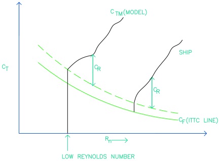
Fig. showing the form factor deduction
One assumption in this is that k is independent of the speed, which is a fair assumption
Another issue is that since the resistance measurement is done at low speeds, errors can have huge implications and one must be very careful in this test.
Another means of finding k value is Prohaska method.
 , by substituting CR as a function of Froude number

We can try to fit a curve to find the value of n and c. But since the errors are not constant throughout the speed range, it can give erroneous results.
Until now we do not have a good way of estimating 3-D frictional resistance.
The model resistance curve is plotted and at low speed it can be treated that (1+k) CFO (as discussed above) is the difference with the ITTC CF line.
Geogism test
Make two models of the ship at two difference scale.
Join same Froude number points to get lines and this is parallel to each other as the CR would be same.
 : for first model
 : for second model
At same Froude number CR is same.
Find the difference, 
 : All are known values and we can find k

Fig. CT versus Rn
If we do not do this (1+k) correction, we are overestimating the total resistance of the ship. In the model case, as we do not take the (1+k) we are attributing more resistance to CR which remains same with ship and model. Since we are over-estimating, instead of spending lot of money on geogism test, we can avoid the form factor correction (k) and estimate the ship resistance. ITTC has said that either of this methods are acceptable and one need to find the form factor only if economics permit it.
References
§ Principles of Naval Architecture. Publisher SNAME
§ Ship Resistance Video Lectures. Publisher NPTEL - A Joint Venture by Indian Institute of Technology & Indian Institute of Science
Other Lessons
Previous - Resistance Types, Resistance - Dimensional Analysis
Next - Wave_Making_Resistance, Other_Components_of_Resistance
О.В. МИТРОФАНОВА, К.С. ФИЛАТОВ
Московский государственный инженерно-физический институт
(технический университет)
|
|