(1)Р Розрахунок за методом окремих коефіцієнтів безпеки здійснюють у відповідності с 2.4 EN 1996-1-1: 2005.
ПРИМІТКА. Також застосовують примітки до 2.4.2 EN 1996-1-1: 2005.
(2)Р Відповідні значення окремих коефіцієнтів для матеріалів γ М застосовують для граничного стану за міцностю в звичайних ситуаціях.
ПРИМІТКА. Чисельні значення γ М приведені в національному додатку. Рекомендовані значення, приведені в 2.4.3 EN 1996-1-1: 2005. Рекомендовані значення для кам'яних конструкций повторно приведені в таблиці нижче.
1 General
1 Scope Part 3 of Eurocode 6
(1)P The scope of Eurocode 6 for Masonry Structures as given in 1.1.1 of
EN 1996-1-1: 2005 applies also to this
EN 1996-3.
NOTE: Eurocode 6 deals only with the requirements for resistance, serviceability and durability of structures. Other requirements are not considered. Eurocode 6 does not cover the special requirements of seismic design.
(2)P EN 1996-3 provides simplified calculation methods to facilitate the design of the following unreinforced masonry walls, subject to certain conditions of application:
— walls subjected to vertical loading and wind loading;
—walls subjected to concentrated loads;
— shear walls;
— basement walls subjected to lateral earth pressure and vertical loads;
— walls subjected to lateral loads but not subjected to vertical loads.
(3)P The rules given in EN 1996-3 are consistent with those given in EN 1996-1-1, but are more conservative in respect of the conditions and limitations of their use.
(4) For those types of masonry structure or parts of structures not covered by (1), the design shall be based on EN 1996-1-1.
(5) This EN 1996-3 applies only to those masonry structures, or parts thereof, that are described in EN 1996-1-1 and EN 1996-2.
(6) The simplified calculation methods given in this EN 1996-3 do not cover the design for
accidental situations.
1.2 Normative references
(1)P The references in 1.2 of
EN 1996-1-1: 2005 apply to this EN 1996-3.
1.3 Assumptions
(1)P The assumptions given in 1.3 of
EN 1990: 2002 apply to this EN 1996-3.
1.4 Distinction between Principles and Application Rules
(1)P The rules of 1.4 of EN 1990: 2002 apply to this EN 1996-3.
1.5 Definitions
1.5.1 General
(1) The terms and definitions given in 1.5 of EN 1990: 2002 apply to this EN 1996-3.
(2) The terms and definitions in 1.5 of
EN 1996-1-1: 2005 apply to this EN 1996-3.
(3) Additional terms and definitions used in this EN 1996-2 are given the meanings contained in clause 1.5.2.
1.5.2 Masonry
1.5.2.1 basement wall
a retaining wall constructed partly or fully below ground level.
1.6 Symbols
(1)P Material-independent symbols are given in 1.6 of EN 1990.
(2)P For the purpose of this standard the symbols given in EN 1996-1-1 apply.
(3)P Other symbols used in this EN 1996-3 are:
bc is the distance apart of cross walls or other buttressing elements;
c is a constant;
fk, s is the characteristic compressive strength of masonry, determined from a simplified
method;
fvdo is the design value of the initial shear strength;
fvdu is the design value of the limit to the shear strength;
ha is the average height of the building;
he is the height of the wall under ground level
hm is the maximum height of a building allowed with the simplified calculation method;
kG is a constant;
l is the length of a wall in the horizontal direction;
lbx is the plan dimension of a building in the x-direction;
lbyis the plan dimension of a building in the y-direction;
lfis the span of a floor;
lf, ef is the effective span of a floor;
lsx is the length of a shear wall orientated in the x-direction;
lsyis the length of a shear wall orientated in the y-direction;
NEd, max is the design value of the maximum vertical load
NEd, min is the design value of the minimum vertical load
qEwd is the design wind load per unit area;
wEk is the characteristic wind load per unit area;
α is the loading ratio;
β is a constant;
ρe is the weight per volume of the soil;
Φ s is the capacity reduction factor.
2 Basis of design
2.1 General
(1)P The design of masonry buildings shall be in accordance with the general rules given in EN 1990.
(2)P Specific provisions for masonry structures are given in section 2 of
EN 1996-1-1: 2005 and shall be applied.
2.2 Basic variables
(1) P Actions shall be obtained from the relevant parts of EN 1991.
(2)P Partial factors for load shall be obtained from EN 1990.
(3)P Properties for materials and construction products and geometrical data to be used for design shall be those specified in EN 1996-1-1, or other relevant hENs of ETAs, unless otherwise indicated in this EN 1996-3.
2.3 Verification by the partial factor method
(1)P The verification by the partial factor method shall be done according to clause 2.4 of EN 1996-1-1: 2005.
NOTE: The notes to 2.4.2 of EN 1996-1-1: 2005 also apply.
(2)P The relevant values of the partial factor for materials γ M shall be used for the ultimate limit
NOTE: The numerical values to be ascribed to the symbol γ M may be found in the National Annex. Recommended values are those as given in clause 2.4.3 of EN 1996-1-1: 2005. The recommended values for masonry are repeated in the table below.
3.3 Характеристичний опір кам'яної кладки на розтяг при вигині
(1) Характеристичний опір кам'яної кладки на розтяг при вигині визначають відповідно до 3.6.3 EN 1996-1-1: 2005.
(2) Спрощений метод визначення характерристичного опору кам'яної кладки на розтяг при вигині з використанням цього документа приведений в Додатку D.
3.4 Початковий характеристичний опір кам'яної кладки зрушенню (зрізу)
(1) Початковий характеристичний опір кам'яної кладки зрушенню (зрізу) fvko
визначають відповідно до 3.6.2
EN 1996-1-1: 2005.
(2) Спрощений метод визначення початкового характеристичного опору кам'яної кладки зрушенню (зрізу) з використанням цього документа приведений в Додатку D.
4 Проектування стін з неармованих кам'яних конструкцій з використанням спрощених методів розрахунку
4.1 Загальні положення
(1)Р Загальна стійкість будівлі, частину якої складають стіни, має бути перевірена.
Примітка. Перевірку допустимо проводити відповідно до 5.4(1) EN 1996-1-1: 2005 або спрощеним методом, який може бути приведений в національному додатку.
4.2 Спрощений метод розрахунку для стін, при дій вертикальних і вітрових навантажень
4.2.1 Умови використання
4.2.1.1 Загальні умови
(1)Р Для використання спрощеного методу мають бути дотримані наступні вимоги:
— висота будівлі над рівнем землі не повинна перевищувати hm; для будівель із скатним дахом висоту визначають як середню висоту h а, вказану на Рисунку 4.1.
3.3 Characteristic flexural strength of masonry
(1) The characteristic flexural strength of masonry should be determined according to 3.6.3 of EN 1996-1-1: 2005.
(2) A simplified method to determine the characteristic flexural strengths of masonry for use in this document is provided in Annex D.
3.4 Characteristic initial shear strength of masonry
(1) The characteristic initial shear strength of masonry, fvko, should be determined according to 3.6.2 of EN 1996-1-1: 2005.
(2) A simplified method to determine the characteristic initial shear strength of masonry for use in this document is provided in Annex D.
4 Design of unreinforced masonry walls using simplified calculation methods
4.1 General
(1)P The overall stability of a building, of which the wall forms a part, shall be verified.
NOTE: The verification may be carried out in accordance with 5.4(1) of EN 1996-1-1: 2005 or from a simplified method, which may be given in the National Annex.
4.2 Simplified calculation method for walls subjected to vertical and wind loading
4.2.1 Conditions for application
4.2.1.1 General conditions
(1)P For use of the simplified method the following conditions shall be complied with:
— the height of the building above ground level shall not exceed hm; for buildings with a slopingroof the height shall be determined as average height h a indicated in Figure 4.1.
Рисунок 4.1 — Визначення середньої висоти
Figure 4.1 ─ Determination of average height
ПРИМІТКА. Чисельні значення позначення hm для використання в країні приведені в національному додатку. Рекомендовані значення hm за класами будівель, наведені в таблиці.
NOTE: The numerical value to be ascribed to the symbol hm for use in a country may be found in its National Annex. Recommended values, given as classes, are given in the table below.
Клас будівлі
Class
hm
20 м
16 м
12 м
— довжина прольоту перекриття між несучими стінами, не повинна перевищувати 7, 0 м;
— довжина прольоту даху між несучими стінами, не повинна перевищувати 7, 0 м, за винятком легкої покрівельної конструкції з кроквяних ферм, в яких довжина прольоту не повинна перевищувати 14, 0 м;
— висота поверху в світу не повинна перевищувати 3, 2 м, якщо загальна висота будівлі не перевищує 7, 0 м; при перевищенні — висота в світу нижнього поверху може складати 4, 0 м;
— власні значення змінних навантажень на перекриття і конструкції даху не повинні перевищувати
5, 0 кН/м2;
— стіни затиснені конструкціями перекриттів і даху в горизонтальному напрямі під прямими кутами до плоскості стіни, або перекриттями і дахом, або іншими способами, наприклад кільцевими балками з відповідною жорсткістю, згідно за 8.5.1.1 EN 1996-1-1: 2005;
— стіни вертикальні по всій висоті;
— перекриття і конструкції даху обпираються, щонайменше, на 0, 4 t товщини стіни, але не менш ніж на 75 мм;
— коефіцієнт повзучості кладки не перевищує 2, 0;
— товщину стіни і міцність на стиск кладки перевіряють на рівні кожного поверху, якщо дані змінні параметри не є однаковими на всіх поверхах.
ПРИМІТКА. Спрощений метод розрахунку для будівель заввишки менш ніж 3 поверхи приведений в Додатку А.
4.2.1.2 Додаткові умови
(1) Для крайніх несучих стін (рисунок 4.2), спрощений метод розрахунку, приведений в 4.2.2, застосовують лише тоді, коли довжина прольоту перекриття lf не перевищує:
— the span of the floors supported by the walls shall not exceed 7, 0 m;
— the span of the roof supported by the walls shall not exceed 7, 0 m, except in the case of a lightweight trussed roof structure where the span shall not exceed 14, 0 m;
— the clear storey height shall not exceed 3, 2 m unless the overall height of the building is greater than 7, 0 m, in which case the clear storey height of the ground storey may be 4, 0 m.
— the characteristic values of the variable actions on the floors and the roof shall not exceed 5, 0 kN/m2;
— the walls are laterally restrained by the floors and roof in the horizontal direction at right angles to the plane of the wall, either by the floors and roof themselves or by suitable methods, e.g. ring beams with sufficient stiffness according to 8.5.1.1 of EN 1996-1-1: 2005
— the walls are vertically aligned throughout their height;
— the floors and roof have a bearing on the wall of at least 0, 4 t of the thickness of the wall but not less than 75 mm;
— the final creep coefficient of the masonry φ ∞ does not exceed 2, 0;
— the thickness of the wall and the compressive strength of the masonry shall be checked at each
storey level, unless these variables are the same at all storeys.
NOTE: A further simplified calculation method, applicable to buildings not exceeding 3 storeys in height, is given in Annex A.
4.2.1.2 Additional conditions
(1) For walls acting as end supports to floors (see Figure 4.2), the simplified calculation method
given in 4.2.2 may be applied only if the floor span lf is not greater than:
7, 0 м, коли NEd£ kGtbfd, (4.1а)
7, 0 m when N Ed ≤ k G t b f d (4.1a)
або менше 4, 5 + 10 t (м) и 7, 0 м, коли fd > 2, 5 Н/мм2, (4.1b)
or the lesser of 4, 5 + 10 t (in m) and 7, 0 m when f d > 2, 5 N/mm², (4.1b)
або менше 4, 5 + 10 t (м) и 6, 0 м, коли fd £ 2, 5 Н/мм2, (4.1c) or the lesser of 4, 5 + 10 t (in m) and 6, 0 m when f d ≤ 2, 5 N/mm², (4.1c)
де
NEd — розрахункове значення зусилля від вертикального навантаження, що діє на даному рівні;
t — фактична товщина стіни або несучого шару багатошарової (порожнистої) стіни, що є крайньою опорою, м;
b — розрахункова ширина, на якій діє корисне вертикальне навантаження;
fd — розрахунковий опір на стиск кам'я-ної кладки;
kG — 0, 2 для елементів кладки групи 1;
— 0, 1 для елементів кладки групи 2, групи 3 і групи 4.
where:
NEd is the design vertical load on the level being considered;
t is the actual thickness of the wall, or the load bearing leaf of a cavity wall, acting as an end
support, in metres;
b is the width over which the vertical load is effective;
fd is the design compressive strength of the masonry;
kG is 0, 2 for Group 1 masonry units;
is 0, 1 for Group 2, Group 3 and Group 4 masonry units.
Рисунок 4.2 — Крайня несуча стіна,
Figure 4.2 ─ Wall acting as end support
(2)Р Крайні несучі стіни, що сприймають вітрові навантаження, проектують відповідно до 4.2.2 лише в тому випадку, якщо:
(2)P Walls acting as end supports to floors or roofs that are subjected to wind loading shall be designed according to 4.2.2 only if:
(4.2)
де:
h — висота поверху в світу;
qEwd — розрахункове вітрове навантаження на стіну, на одиницю площі стіни;
NEd — розрахункове значення зусилля від діючого вертикального навантаження, (від мінімального навантаження на стіну у верхній її частині на рівні даного поверху);
b — розрахункова ширина, на якій діє корисне вертикальне навантаження;
t — фактична товщина крайньої несучої стіни або несучого шару багатошарової (порожнистої) крайньої стіни, м;
a — коефіцієнт відносного рівня навантаження, рівний с1, с2 — постійні коефіцієнти, що отримуються з таблиці 4.1
where:
h is the clear storey height;
qEwd is the design wind load on the wall per unit area of the wall;
NEd is the design value of the vertical load giving the least severe effect on the wall at the top of
the storey considered;
b is the width over which the vertical load is effective;
t is the actual thickness of the wall, or the load bearing leaf of a cavity wall, acting as an end
support;
a is constant - c1, c2 are constants derived from Table 4.1.
Таблиця 4.1 — Постійні коефіцієнти с1 і с2
Table 4.1 — Constants c1 and c2
α
с1
с2
0, 05
0, 10
0, 20
0, 30
0, 50
0, 12
0, 12
0, 14
0, 15
0, 23
0, 017
0, 019
0, 022
0, 025
0, 031
Примітка. Допускається лінійна інтерполяція.
NOTE: Linear interpolation is permitted
ПРИМІТКА. В Додатку С приведений спрощений метод розрахунку стін, при дії рівномірного бокового тиску (горизонтальному навантаженню), але його допустимо використовувати замість формули (4.2) для визначення товщини t, якщо розрахункове вертикальне навантаження, що викликає максимальне зусилля, дорівнює kGbtfdабо менше, где kG, b, tи і fd відповідають 4.2.1.2.
4.2.2 Визначення міцності стіни при дії розрахункового вертикального зусилля
4.2.2.1 Загальні положення
(1)Р При визначенні міцності в граничному стані по несучій здатності перевіряють умовою:
NOTE: Annex C gives a simplified method for lateral load design, but it may be used to obtain the thickness t instead of equation (4.2) if the design vertical load giving the most severe effect is kGbtfd or less, where k, b, t and fd are asdescribed in 4.2.1.2.
4.2.2 Determination of design vertical load resistance of a wall
4.2.2.1 General
(1)P Under the ultimate limit state it shall be verified that:
NRd = FsfdA, (4.4)
де
Фs — коефіцієнт зменьшення для урахування гнучкості та ексцентриситету навантаження, що визначається за 4.2.2.3;
fd — розрахунковий опір на стиск камяної кладки;
A — площа завантаженого горизонтального поперечного перетину стіни, (або розрахункова площа горизонтального поперечного перетину стіни).
4.2.2.3 Коефіцієнт зменшення для врахування гнучкості, початкового ексцентриситету навантаження, довготривалого навантаження і повзучості
(1) Коефіцієнт зменшення для урахування гнучкості, початкового ексцентриситету навантаження, тривалого навантаження і повзучості Фs:
— для проміжних стін визначають за формулою (4.5a):
where:
Φ s is the capacity reduction factor allowing for the effects of slenderness and eccentricity of
the loading, obtained from 4.2.2.3;
fd is the design compressive strength of the masonry;
A is the loaded horizontal gross sectional area of the wall.
4.2.2.3 Capacity reduction factor
(1) The capacity reduction factor Φ s for intermediate walls should be determined from equation (4.5a).
(4.5а)
— для крайніх несучих стін Фs визначають по меншому значенню, отриманому за формулою (4.5а) або за формулою
For walls acting as end supports to the floors Φ s should be determined from the lesser of equation (4.5a) or
(4.5б)
- для верхньої частини крайніх несучих стін, (Фs визначають по меншому значенню, отриманому по формулах (4.5а), (4.5b) або по формулі
For walls at the highest level acting as end support to the top floor or roof Φ s should be determined from the lesser of equations (4.5a), (4.5b) or
Fs= 0, 4;
де:
hef - приведена висота стіни (див. 4.2.2.4);
tef — ефективна товщина стіни, що визначається відповідно до 5.5.1.3
EN 1996-1-1: 2005 або tef = t — для одношарової стіни (суцільна стіна);
— для багатошарової (з порожнечами) стіни з анкерними (гнучкими) зв'язками але не менше ніж ntmin, де ntmin — мінімальна кількість зв'язків на м2; t1 і t2 - фактична товщину шарів з модулем пружності ненавантаженого шару рівним або більшим ніж 90 % модуля пружності навантаженого шару;
lf, ef — розрахунковий (ефективний) прольот перекриття, (м), для якого стіна є крайньою опорою, :
lf, ef = lf — для конструкцій перекриття, вільно обпертих в одному (розрахунковому) напрямку;
lf, ef = 0, 7 lf — для суцільних нерозрізних конструкцій перекриттів, обпертих за всіма сторонами;
lf, ef = 0, 7 lf— для перекриттів, вільно обпертих в двох напрямках, якщо довжина прольоту обпертого на дану несучу стіну, не перевищує 2 lf;
lf, ef = 0, 5 lf — для суцільних нерозрізних конструкцій перекриття, що обпертого в двох напрямках, якщо довжина прольоту обпертого на дану несучу стіну, не перевищує 2 lf;
Fs - коефіцієнт зменшення для підрахунку гнучкості, початкового ексцентриситету навантаження, тривалого навантаження і повзучості.
ПРИМІТКА. Чисельне значення ntmin для використання в країні приведене в національному додатку; рекомендоване значення дорівнює 2.
(4.5с)
where:
hef is the effective height of the wall (see 4.2.2.4);
tef is the effective thickness determined in accordance with 5.5.1.3 of EN 1996-1-1: 2005 or
tef = t for a single leaf wall
for a cavity wall with wall ties of not less than ntmin, the minimum number
of wall ties per m2, where t1 and t2 are the actual thicknesses of the leaves and where the modulus of elasticity of the unloaded leaf is equal to or greater than 90% of that of the loaded leaf.
lf, ef is the effective span of the floor in metres for which the wall is acting as end support, as
follows:
lf, ef = lf for simply supported floor structures;
lf, ef = 0, 7 lf for continuous floor structures;
lf, ef= 0, 7 lf for simply supported floors spanning in 2 directions where the supported length on the considered wall is not greater than two times lf;
lf, ef= 0, 5 lf for continuous floors spanning in 2 directions where the supported length on the considered wall is not greater than two times lf;
Φ s is the capacity reduction factor which incorporates the buckling effect, the initial eccentricity, the eccentricity due to loads and the creep effect.
NOTE: The value of ntmin for use in a country may be found in its National Annex; the recommended value is 2.
4.2.2.4 Приведена висота стін
(1) Приведену висоту стіни визначають за
формулою
4.2.2.4 Effective height of walls
(1) The effective height may be determined by
hef= ρnh (4.6)
Відсутнє посилання на рис.4.3!
Рисунок 4.3 — Стіна, жорстко затиснута між перекриттями або конструкціями даху
Figure 4.3 ─ Rotational restraint provided by floors or roof
(II) Для стін, затиснених у верхній і нижній частині (наприклад, між межповерховими поясами жорткості або дерев'яними перекриттями), але не затиснених жорстко (від повороту) перекриттями або конструкціями даху (рисунок 4.4)
(II) For all walls laterally restrained at top and bottom only (e.g. by ring beams of appropriate stiffness or timber floors) but not rotationally restrained by the floors or roof (see Figure 4.4):
Рисунок 4.4 — Відсутність жорсткого затискання (від повороту) перекриттями
і конструкціями даху
Figure 4.4 ─ No rotational restraint provided by floors or roof
(III) Для стін, затиснених на рівні нижнього і верхнього перекриттів і з однієї вертикальної сторони (рисунок 4.5):
— в разі жорсткого затискання лише на рівні верхнього і нижнього пере-криттів, як встановлено в (i), якщо стіна не є крайньою несучою;
≤ 1, 0 —для всіх інших випадків в (I) і (II)
де:
h — висота поверху в світу;
l — відстань від вертикально затисненого краю до вільного краю стіни;
(III) For walls laterally restrained at top and bottom and at one vertical edge (see figure 4.5):
in the case of rotational restraint at top and bottom only as in (i) above if the wall is not acting as end support of the floor;
≤ 1, 0 in all other cases in (i) and (ii) above
where:
h is the clear storey height;
l is the distance from the vertically supported edge to the free edge.
Рисунок 4.5 — Стіна, затиснена на рівні верхнього і нижнього перекриттів і
з однієї вертикальної сторони
Figure 4.5 ─ Wall laterally restrained at top and bottom and at one vertical edge
(IV) Для стін, затиснених на рівні верхнього та нижнього перекриттів та по двох вертикальних сторонах (рисунок 4.6):
в разі жорсткого затискання лише на рівні верхнього і нижнього перекриттів, як встановлено в (i), якщо стіна не є крайньою несучою;
≤ 1, 0 — у всіх інших випадках в (I) і (II)
де h — висота поверху в світу;
l — відстань між опорами по бокових вертикальних сторін.
(IV) For walls laterally restrained at top and bottom and at two vertical edges (see Figure 4.6):
in the case of rotational restraint at top and bottom only as in (i) above if the wall is not acting as end support of the floor;
≤ 1, 0 in all other cases in (I) and (II) above where:
h is the clear storey height;
l is the distance between the supports at the vertical edges.
Рисунок 4.6 — Стіна, затиснена на рівні верхнього і нижнього перекриттів
і по двох вертикальних сторонах
Figure 4.6 ─ Wall laterally restrained at top and bottom and two vertical edges
4.2.2.5 Коефіцієнт гнучкості для стін
(1) Коефіцієнт гнучкості для стін hef/tef не повинен перевищувати 27.
4.3 Спрощений метод розрахунку для стін при дії зосереджених навантажень
(1) Міцність розрахункового перетину стіни, виконаної з кладки, при дії зосередженого (локального) навантаження NRdc можна отримати за:
— формулою (4.7), якщо кладка виконана з елементів групи 1;
— формулою (4.8), якщо кладка виконана з елементів групи 2, 3 або 4
4.2.2.5 Slenderness ratio of walls
(1) The slenderness ratio of a wall hef/ tef should not be greater than 27.
4.3 Simplified calculation method for walls subjected to concentrated loads
(1) The design value of the vertical concentrated load resistance of a wall, NRdc, may be obtained from:
— equation (4.7), for masonry made with Group 1 units;
— equation (4.8), for masonry made with Group 2, 3 or 4 units.
але не більше 1, 5 fdAb; (4.7)
NRdc= fdAb(4.8)
де:
а1 - відстань від краю стіни до найближчого краю опорної поверхні, завантаженого зосередженим навантаженням (рисунок 4.7);
hc hc - висота стіни від підлоги до площини навантаження (рисунок 4.7);
Ab - площа стіни, на яку передається навантаження;
where:
a1 is the distance from the end of the wall to the nearest edge of the bearing area of the
concentrated load (see figure 4.7);
hc is the height of the wall from the floor to the level of the load (see figure 4.7);
Abis the loaded area.
Рисунок 4.7 — Вертикальна проекція стіни із зосередженим навантаженням
відносно до а1 і hс
Figure 4.7 ─ Elevation of wall with a concentrated load, in relation to a1 and hc
за умови, що:
— площа опорної поверхні, на яку передається зосереджене навантаження, не перевищує 1/4 площі поперечного перетину стіни і не перевищує значення 2t2, де t — товщина стіни;
—ексцентриситет зосередженого (локального) навантаження, що вимірюється від центра тяжіння стіни, не перевищує t /4;
— міцність стіни в середній її частині за висотою поверху визначають відповідно до 4.2 при умові, що тиск в кладці нижче тиску на опорну ділянку і зосереджене навантаженя розподіляється під кутом 60° до горизонтальної плоскості.
4.4 Спрощений метод розрахунку стін жорсткості
4.4.1 Перевірка міцності при дії зусиль зрізу (зрушення)
(1)Р В граничному стані за міцністю перевіряють умову
provided that:
— the bearing area under the concentrated load neither exceeds ј of the cross sectional area of
the wall nor exceeds the value 2 t2, where t is the thickness of the wall;
— the eccentricity of the load from the centre plane of the wall is not greater than t /4;
— the adequacy of the wall at its middle height section is verified in accordance with 4.2,
assuming the concentrated load spreads at an angle of 60°.
4.4 Simplified calculation method for shear walls
4.4.1 Verification of shear resistance of walls
(1)P Under the ultimate limit state, it shall be verified that:
VEd≤ VRd(4.9)
де:
VEd — розрахункове значення поперечної сили від навантажень і зусиль;
VRd— міцність розрахункового перетину стіни з кладки при дії поперечної сили.
ПРИМІТКА. Спрощений метод розрахунку жорсткості при проектуванні стін для будівель, висота яких не перевищує три поверхи, наведений в Додатку А3.
4.4.2 Міцність розрахункового перерізу стіни при дії поперечної сили на зріз (зрушення)
(1) Міцність розрахункового прямокутного перерізу стіни при дії поперечної сили на зріз (зрушення) VRd визначають за формулою
where:
VEd is the design shear load on the wall,
VRd is the design shear resistance of the wall.
NOTE: A further simplified calculation method of designing shear walls for buildings not exceeding 3 storeys in height is given in Annex A3.
4.4.2 Design shear resistance
(1) The design shear resistance VRdof a rectangular section may be determined as follows:
(4.10а)
де:
сv дорівнює 3 — для кладки із заповненими вертикальними швами або дорівнює 1, 5 для кладки з незаповненими вертикальними швами;
l - довжина стіни в напрямку вертикальної плоскості зрізу;
eEd - ексцентриситет стискаючого вертикального навантаження в даному поперечному перерізі, що визначається за формулою
where:
cv is 3 for masonry with filled perpend joints
or 1, 5 for masonry with unfilled perpend joints;
l is the length of the wall in the bending direction;
eEd is the eccentricity of the compressive load
in the cross section being considered
(4.10b)
але не менше l/6MEd — розрахункове значення згинального моменту, діючого в даному поперечному перерізі;
NEd— розрахункове значення стискаючого зусилля від вертикального навантаження, діючого в даному поперечному перерізі;
t — товщина стіни;
fvdo — початковий розрахунковий опір на зріз (зрушення) кам'яної кладки, що дорівнює fvko, поділеному на γ M, відповідно до 3.4;
fvdu — граничний розрахунковий опір на зріз (зрушення) кам'яної кладки відповідно до 3.6.2(3) і 3.6.2(4) EN 1996-1-1: 2005.
ПРИМІТКА. Значення межі міцності на зрушення приведені в EN 1996-1-1: 2005.
(2) Формулу (4.10а) допустимо використовувати, якщо:
— кладка виконана не з порожнистих елементів з частковим (смуговим) заповненням розчином горизонтальних швів;
— будівельний розчин є:
— розчином загального призначення відповідно до 3.2 EN 1996-1-1: 2005 або
— розчином, що укладається тонким шаром, завтовшки від 0, 5 до 3, 0 мм, відповідно до
EN 998-2, або
— легким розчином відповідно до EN 998-2;
— шви, заповнені розчином, задовольняють вимогам 8.1.5 EN 1996-1-1: 2005;
— NEd ≤ 0, 5 l t fd..
4.5 Спрощений метод розрахунку для цокольних стін (стін підвалів) при дії бокового тиску грунту
(1) Наступний спрощений метод допустимо використовувати при проектуванні цокольних стін (стін підвалів), при боковому тиску грунту при дотриманні наступних умов:
— висота цокольної стіни на просвіт h ≤ 2, 6 м і товщина стіни t ≥ 200 мм;
— перекриття над цокольним поверхом є жорстким диском і здатне витримувати горизонтальні зусилля, що виникають внаслідок тиску грунту;
— характеристичне прикладене навантаження на поверхню грунту за площею дії тиску грунту на цокольну стіну не перевищує 5 кН/м2, і зосереджене вертикальне навантаження на грунт в межах 1, 5 м від стіни не перевищує 15 кН (рисунок 4.8);
— поверхня грунту знаходиться близько від цоколю стіни і висота насипу не перевищує висоту стіни;
— гідростатичний тиск на стіну відсутній або не впливає на розрахункові горизонтальні зусилля на стіну;
— відсутня площина ковзання, що створюється, наприклад, за допомогою гідроізоляційної прокладки.
ПРИМІТКА. Для перевірки дії внаслідок тиску грунту використовують коефіцієнт тертя кладки стіни на площині контакту з фундаментом, що дорівнює 0, 6.
(2) Перевірку міцності стіни виконують за наступними формулами:
not taken less than l/6MEd is the design value of the moment in the cross section being considered;
NEd is the design value of the compressive load in the cross section being considered;
t is the thickness of the wall;
fvdo is the design value of the initial shear strength equal to fvko, according to 3.4, divided by γ M;
fvdu is the design value of the limit to the shear strength according to 3.6.2(3) and 3.6.2(4) of EN 1996-1-1: 2005.
NOTE: The values of the limit to the shear strength can be found in EN 1996-1-1: 2005.
(2) Equation (4.10a) may be used when:
— the masonry is not shell bedded masonry;
— the mortar is either:
—general purpose mortar in accordance with 3.2 of EN 1996-1-1: 2005 or;
— thin layer mortar in beds of thickness 0, 5 mm to 3, 0 mm in accordance with EN 998-2 or;
— lightweight mortar in accordance with EN 998-2;
— the mortar joints satisfy the requirement of 8.1.5 of EN 1996-1-1: 2005;
— NEd ≤ 0, 5 l t fd.
4.5 Simplified calculation method for basement walls subject to lateral earth
pressure
(1) The following simplified method may be used for designing basement walls subject to lateral earth pressure providing the following conditions are fulfilled:
— the clear height of the basement wall, h ≤ 2, 6 m, and the wall thickness, t ≥ 200 mm;
— the floor over the basement acts as a diaphragm and is capable of withstanding the forces resulting from the soil pressure;
— the characteristic imposed load on the ground surface in the area of influence of the soil pressure on the basement wall does not exceed 5 kN/m² and no concentrated load within 1, 5 m of the wall exceeds 15 kN, see figure 4.8;
— the ground surface does not rise away from the wall and the depth of fill does not exceed the wall height;
— there is no hydrostatic pressure acting on the wall;
— either no slip plane is created, for example by a damp proof course or measures are taken to resist the shear force.
NOTE: For the verification of the shear action due to earth pressure a coefficient of friction of 0, 6 has been used.
(2) The design of the wall may be derived on the basis of the following expressions, as appropriate:
(4.11)
, (4.12)
де:
NEd, max - максимальне розрахункове значення зусилля від вертикального навантаження, яке визначене для розрахункового горизонтального перерізу стіни на відстані 1/2hе від низу стіни;
NEd, min -мінімальне розрахункове значення зусилля від вертикального навантаження, яке визначене для розрахункового горизонтального перерізу стіни на відстані 1/2hе від низу стіни;
b - ширина стіни (розрахункової ділянки);
bc - відстань між поперечними стінами або іншими несучими елементами;
h - висота цокольної стіни (стіни підвалу) в світу;
he - висота стіни нижча за рівень землі;
t - товщина стіни;
re - на кубічний метр грунту (об´ ємна вага ґрунту);
fd - розрахунковий опір на стиск кам'яної кладки;
b - приймають рівним 20, якщо bc ≥ 2 h; прий- мають рівним 60-20 bc /2h, якщо h < b c < 2 h, приймають рівним 40, якщо bc ≤ h.
where:
NEd, max is the design value of the vertical load on the wall giving the most severe effect at the
mid-height of the fill;
NEd, min is the design value of the the vertical load on the wall giving the least severe effect at
the mid-height of the fill;
b is the width of the wall;
bc is the distance apart of cross walls or other buttressing elements;
h is the clear height of the basement wall;
he is the height of the wall under ground level;
t is the wall thickness;
ρe is the weight per cubic metre of the soil;
fd is the design compressive strength of the masonry;
β is 20 when bc ≥ 2h, is 60 - 20 b c / h when
h < b c < 2 h, is 40 when b c ≤ h.
Рисунок 4.8 — Параметри для розрахунків цокольних стін (поперечний перерізі і фрагменті плану):
(а) зосереджене вертикальне навантаження на грунт в межах 1, 5 м відстіни не перевищує 15 кН; (b)— характеристичне навантаження на грунт ≤ 5 кН/м2
Figure 4.8 ─ Variables for basement walls shown in cross section and plan
(a) No point load ≥ 15 kN within 1, 5 metres of the wall, measured in horizontal direction,
(b) The characteristic imposed load on the ground ≤ 5 kN/m².
4.6 Спрощений метод розрахунку при проектуванні стін, при дії розрахункового бокового навантаження за відсутності вертикальних навантажень
(1) Спрощений метод розрахунку для визначення мінімальної товщини і граничних розмірів внутрішніх стін, за відсутності вертикальних навантажень, окрім навантажень від власної ваги в межах даної ділянки стіни, але які мають змінні умови бокового затискання, та обумовлені певними обмеженнями, приведений в Додатку В для стін з обмеженим боковим навантаженням.
4.7 Спрощений метод розрахунку при проектуванні стін, при дії рівномірного бокового тиску (навантаження) за відсутності вертикальних навантажень
(1) Стіни, при дії рівномірного бокового тиску (навантаження), допускається проектувати за спрощеним методом розрахунку.
ПРИМІТКА. Спрощений метод розрахунку для визначення мінімальної товщини і граничних розмірів внутрішніх стін, за відсутності вертикальних навантажень, окрім навантажень від власної ваги в межах даної ділянки стіни, але які мають змінні умови бокового затискання, що обумовлені певними обмеженнями, приведений в Додатку С для стін, при дії рівномірного бокового розрахункового тиску (розрахункового навантаження).
4.6 Simplified calculation method for the design of walls subjected to limited lateral
load but no vertical loads
(1) A simplified calculation method for determining the minimum thickness and limiting dimensions of internal walls, not subjected to vertical loads other than self-weight, but having
variable conditions of lateral restraint, conditional on certain restrictions, is given in Annex B for walls with a limited lateral load.
4.7 Simplified calculation method for the design of walls subjected to uniform lateral
load but no vertical loads
(1) Walls subjected to uniform lateral loads may be designed by a simplified method.
NOTE: A simplified calculation method for determining the minimum thickness and limiting dimensions of walls having variable conditions of lateral restraint and not subject to vertical loads other than self-weight is given in Annex C for walls subject to a uniform lateral design load.
ДОДАТОК А
(довідковий)
Спрощений метод розрахунку для неармованої кладки стін будівель, що не перевищують три поверхи
А.1 Загальні умови вживання
(1) Спрощений метод розрахунку, приведений в цьому додатку, допустимо використовувати для будівель, якщо дотримуються наступні вимоги:
— по висоті будівля не перевищує три поверхи над рівнем перекриття першого поверху;
— стіни закріплені від горизонтальних переміщень міжповерховими перекриттями і конструкціями даху під прямими кутами до плоскості стіни, або затиснені жорстко міжповерховими перекриттями і конструкціями даху або відповідним способом, наприклад міжповерховими поясами жорсткості;
— перекриття і конструкції даху обпираються не менше чим на 2/3 товщини стіни, але не менш ніж на 85 мм;
— висота поверху напросвіт не перевищує 3, 0 м;
— мінімальні прольоти конструкцій перекриттів не менше 1/3 висоти поверху;
— характеристичні значення навантаження від змінних дій на міжповерхові перекриття і конструкції даху не перевищують 5, 0 кН/м2;
— максимальний прольот перекриття напросвіт складає 6, 0 м;
— максимальний прольот конструкцій даху напросвіт складає 6, 0 м, за винятком легких конструкцій даху, прольот яких не перевищує 12, 0 м;
— коефіцієнт гнучкості he/tef для внутрішніх і зовнішніх стін не перевищує 21;
де
hef — приведена висота стіни відповідно до 4.2.2.4;
tef — приведена товщина, що визначається відповідно до 4.2.2.3.
А.2 Міцність розрахункового перетину кладки стіни при дії вертикального повздовжнього зусилля
(1) Міцність розрахункового перерізу стіни при дії вертикального повздовжнього зусилля NRd визначають за формулою:
ANNEX A
(Informative)
Simplified calculation method for unreinforced masonry walls of buildings not
greater than 3 storeys
A.1 General conditions for application
(1) For buildings the simplified calculation method given in this annex may be used, provided the following conditions are fulfilled.
— the building does not exceed 3 storeys in height above the ground floor level;
— the walls are laterally restrained by the floors and roof in the horizontal direction at right angles to the plane of the wall, either by the floors and roof themselves or by suitable methods, for example ring beams with sufficient stiffness;
— the floors and roof have a bearing on the wall of at least 2/3 of the thickness of the wall but not
less than 85 mm;
— the clear storey height does not exceed 3, 0 m;
— the minimum plan dimension is at least 1/3 of the height;
— the characteristic values of the variable actions on the floors and the roof do not exceed 5, 0 kN/m²;
— the maximum clear span of any floor is 6, 0 m;
—the maximum clear span of the roof is 6, 0 m, except in the case of light weight roof construction where the span does not exceed 12, 0 m;
—the slenderness ratio, hef / tef, of internal and external walls is not greater than 21;
where:
hef is the effective height of the wall in accordance with 4.2.2.4;
tef is the effective thickness determined in accordance with 4.2.2.3.
A.2 Design vertical load resistance of the wall
(1) The design vertical load resistance N Rd is given by:
NRd = cAfd A (A.1)
де
cA =0, 50, якщо hef/tef ≤ 18;
=0, 36, якщо hef/tef > 18 and ≤ 21;
fd — розрахунковий опір на стиск кам'яної кладки;
А — площа поперечного перерізу несучої стіни, за винятком отворів.
А.3 Стіни жорсткості без перевірки опору вітровому навантаженню
(1) Стіни жорсткості допустимо проектувати без перевірки опору вітровому навантаженню, якщо їх розташування є достатнім для забезпечення стійкості будівлі при дії горизонтальних сил в двох перпендикулярних напрямках.
(2) Розташування стін жорсткості можна розглядати як достатнє, якщо:
— характеристичне вітрове навантаження не перевищує 1, 3 кН/м2;
— дві стіни або більш розташовані в двох перпендикулярних напрямках;
— стіни жорсткості є несучими і міцність стін жорсткості при дії розрахункових навантажень, за винятком зусиль від вітрового навантаження, перевіряють відповідно до 4.2, приймаючи як розрахунковий опір кладки на стиск 0, 8 fk;
— розташування стін жорсткості в горизонтальній проекції (на плані) майже симетрично в обох напрямках (рисунок А.2) або, щонайменше, в одному напрямку, якщо відношення
lbx / lby не перевищує 3;
— у горизонтальній проекції (на плані) осі стін жорсткості не зходяться в одній точці;
— сума площин стін жорсткості в кожному з перпендикулярних напрямків, враховуючи лише ділянки стін постійного перерізу довжиною більше 0, 2 htot, за винятком пілястр і полиць таврового перерізу ділянок стін, задовольняє наступним відношенням:
та (А.2)
where:
cA = 0, 50 if hef/tef ≤ 18
= 0, 36 if hef/tef > 18 and ≤ 21;
fd is the design compressive strength of the masonry;
A is the loaded horizontal gross cross-sectional area of the wall, excluding any openings.
A.3 Shear walls without verification of wind load resistance
(1) Shear walls may be designed without verification of the wind load resistance, if the
arrangement of shear walls is sufficient to stiffen the building against horizontal forces in two perpendicular directions.
(2) The arrangement of shear walls may be presumed to be sufficient if:
— the characteristic wind load does not exceed 1, 3 kN/m²;
— there are two walls or more in both perpendicular directions;
— the shear walls are load bearing and the load resistance of the shear walls excluding wind
loading is verified in accordance with 4.2 assuming a reduced compressive strength of masonry of 0, 8 fk;
— the layout of the shear walls is approximately symmetrical in plan in both directions (see Figure A.2) or at least in one direction if the ratio lbx/ lby is not greater than 3;
— in the plan the centre lines of the shear walls do not meet in one point;
— the sum of the web areas of shear walls in each perpendicular direction, considering only webs with a length of more than 0, 2 htot and excluding flanges, sati
sfies the following relationship:
(А.2)
де lbx, де
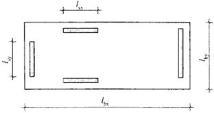
lbx, lby - відстані (довжина і ширина) в горизонтальній проекції (на плані) даної будівлі або його ділянки, де lbx ≥ lby;
lsx, lsy — довжина стін жорсткості (рису-
нок А.1 і рисунок А.2);
htot— висота будівлі;
сs — сt ci wEk;сt — постійний коефіцієнт, залежний від α, що отримується з таблиці А.1, м2/кН;
ci = 1, 0для прямокутних стін жорсткості;
= 0, 67 для стін жорсткості двотаврової форми перерізу з площею полиці більш 0, 4 t l (рисунок А.1);
a— середнє значення відношення NEd/А fd для даних стін жорсткості;
NEd — розрахункове значення зусилля від вертикального навантаження в стіні жорсткості;
А — площа поперечного перерізу стіни;
fd — розрахунковий опір стиску кам'яної кладки;
wEk — характеристичне вітрове навантаження, кН/м2
where:
lbx, lby are the plan dimensions of the building considered where lbx ≥ lby;
lsx, lsy are the shear wall lengths (see Figure A.1 and Figure A.2);
htot is the height of the building;
cs - ctci wEk;
ct is a constant depending on α, obtained from
Table A.1, in m² /kN;
ci = 1, 0 for rectangular shear walls
= 0, 67 for I-profiled shear walls with flange areas greater than 0, 4 t l (see Figure A1);
α is the average of the ratio NEd/А fd of the shear walls being considered;
NEd is the design value of the vertical load in a shear wall;
A is the cross-sectional area of a shear wall;
fd is the design compressive strength of the masonry;
wEk is the characteristic wind load, in kN/m².
Рисунок А.1 — Горизонтальна проекція стін жорсткості і вимога до двотаврової форми перерізу
Figure A.1 ─ Plan of shear walls and requirement for I-shapes
Рисунок А.2 — Розташування стін жорсткості на плані
Figure A.2 ─ Layout of shear walls
Таблица А.1 — Значения сt, м2/кН
Table A.1 ─ Values of ct, m² /kN
a
fk, Н/мм2 N/mm2
0, 2
0, 3
0, 4
0, 5
0, 6
0, 7
0, 0192
0, 0128
0, 0095
0, 0075
0, 0095
0, 0128
0, 0095
0, 0064
0, 0048
0, 0038
0, 0048
0, 0064
0, 0064
0, 0042
0, 0032
0, 0025
0, 0032
0, 0042
0, 0048
0, 0032
0, 0024
0, 0019
0, 0024
0, 0032
ПРИМІТКА. Допускается лінійна інтерполяція.
NOTE: Linear interpolation is permitted.
ДОДАТОК В
(довідковий)
Спрощений метод розрахунку при проектуванні внутрішніх стін при відсутності вертикальних навантажень, окрім навантажень від власної ваги стін в межах висоти поверху, з обмеженим горизонтальним (боковим) навантаженням
(1) Використання правил, приведених в цьому додатку, залежить від наступних вимог дотримання розмірів і вимог до будівництва:
— висота стіни в світу (h) не перевищує 6, 0 м;
— довжина стіни (l) між елементами кон-струкції, що забезпечує затискання та пере-шкоджає горизонтальному переміщенню, не перевищує 12, 0 м;
— товщина стіни, без урахування штукатурки, складає не менше 50 мм;
— елементи кладки (камені і блоки), що використані для будівництва стін, можуть бути будь-якого типу по EN 1996-1-1: 2005, груп 1, 2, 3 і 4.
ПРИМІТКА. Затискання, що перешкоджає горизонтальному переміщенню на рівні низу верхнього перекриття або по бокових вертикальних гранях або на рівні низу верхнього перекриття і по бокових вертикальних гранях стіни, повинні запобігати деформаціям сполучних елементів конструкції (анкерів), залежні від часу (наприклад, внаслідок деформації повзучості залізобетонних конструкцій перекриття і бетонних елементів підлоги), і їх проектують з урахуванням цих деформацій.
(2) Правила, наведені в даному пункті, застосовують лише у разі, коли:
— стіна розташована всередині будівлі;
— на зовнішній фасад будівлі не виходять двері великих розмірів або аналогічні отвори;
— горизонтальне (бокове) навантаження на стіну обмежене навантаженням від людей і невеликих меблів в кімнатах з невеликими групами людей (наприклад, кімнатах і коридорах багатоквартирних житлових будівель, офісів, готелів і т. д.);
— стіна не сприймає постійні або змінні дії (в т.ч. вітрове навантаження), окрім навантаження від власної ваги;
— стіну не використовують як опору для таких важких предметів як меблі, санітарно-
технічне або нагрівальне устаткування;
ANNEX B
(Normative)
Simplified calculation method for the design of internal walls not subject to vertical loads and with limited lateral load
(1) Use of the rules given in this annex is dependent on the following dimensional and
constructional requirements being adhered to:
- the clear height (h) of the wall does not exceed 6, 0 m;
- the clear length (l) of the wall between structural members that give lateral restraint does not
exceed 12, 0 m;
- the thickness of the wall, excluding any plaster, is not less than 50 mm;
- the masonry units used for the wall construction may be any of the types referred to in
EN1996-1-1: 2005 under Groups 1, 2, 3 and 4.
NOTE: Lateral restraints at the top, or sides, or top and sides, of a wall may need to cope with time dependent movements of the connecting structural parts (e.g. deflection due to creep of a concrete floor) and should be designed accordingly.
(2) The rules given in this clause apply only in circumstances where:
— the wall is situated inside a building;
— the external facade of the building is not pierced by a large door, or similar openings;
— the lateral loading on the wall is limited to loads from people and small furniture in rooms with small crowds of people (e.g. rooms and corridors in apartments, offices, hotels etc.);
— the wall is not subjected to any permanent or exceptional variable actions (including wind
loading), other than that due to its self weight;
— the wall is not used as a support for heavy objects such as furniture, sanitary or heating equipment;
— на стійкість стіни не впливає деформація інших частин будівлі (наприклад, прогини перекриттів) або дії з середини будівлі;
— врахований вплив наявності дверних або інших отворів в стіні (методи проектування стін з отворами (4));
— врахований вплив наявності жолобів в стіні.
(3) Мінімальну товщину і граничні розміри стіни визначають за рисунком В.1, на якому приведені наступні умови бокового затискання стіни:
— тип а: стіни, затиснені з чотирьох сторін;
— тип b: стіни, затиснені за всіма сторонами, за винятком однієї вертикальної сторони;
— тип с: стіни, затиснені за всіма сторонами, за винятком верхнього краю;
— тип d: стіни, затиснені лише у верхнього і нижнього краю.
(4) Мінімальну товщину і граничні розміри стін з отворами також визначають за рисунком В.1 за умови, що тип стіни отриманий на підставі Рисунка В.2.
Вплив отворів в стіні можна не враховувати за наступних умов:
— якщо сукупна площа отворів не перевищує 2, 5 % від площі стіни; та
— якщо максимальна площа будь-якого окремого отвору не перевищує 0, 1 м2, і довжина або ширина отвору не перевищує 0, 5 м.
(5) Тип стіни з отвором слід розглядати як тип b для стін, в якому l більше l1 і l2 (рисунок В.2).
(6) Для типа с стін з отвором цей додаток не застосовують.
(7) Для типа d стін з отворами цей додаток застосовують для лівої, середньої і правої частини стіни, якщо l3 ≥ 2/3 l і l3 ≥ 2/3 h (рисунок В.3).
— the stability of the wall is not adversely affected by the deformation of other parts of the
building (e.g. by deflection of floors) or by operations within the building;
— the effect of any door or other openings
formed in the wall is taken into account (see (4) for methods of designing walls with openings);
— the effect of any chases in the wall is taken into account.
(3) The minimum thickness and limiting dimensions of the wall may be determined from Figure B.1 which provides for the following conditions of lateral restraint to the wall:
— type a: walls restrained along 4 edges;
— type b: walls restrained along all edges, except for 1 vertical edge;
— type c: walls restrained along all edges, except at the top edge;
— type d: walls restrained along the top and bottom edges only.
(4) For walls with openings the minimum thickness and limiting dimensions may also be determined from Figure B.1 provided that the type of wall is derived from the basis illustrated in Figure B.2.
The effect of openings in the wall may be ignored in the following circumstances:
— where the aggregated area of the openings is not greater than 2, 5 % of the area of the wall;
and
— where the maximum area of any individual opening is not greater than 0, 1 m² and the length or width of an opening is not greater than 0, 5 m.
(5) Type a wall with an opening should be considered as a type b wall in which l is the greater of l1 and l2, see Figure B.2.
(6) For a type c wall with an opening this annex is not applicable.
(7) For a type d wall with openings this annex is applicable for the left, middle and the right part ofthe wall if l3 ≥ 2/3 l and l3 ≥ 2/3 h, see Figure B.3.)


 (4.2)
(4.2) с 1, с 2 — постійні коефіцієнти, що отримуються з таблиці 4.1
 (4.5а)
 (4.5б)
 — для багатошарової (з порожнечами) стіни з анкерними (гнучкими) зв'язками але не менше ніж n tmin, де ntmin — мінімальна кількість зв'язків на м2; t 1 і t 2 - фактична товщину шарів з модулем пружності ненавантаженого шару рівним або більшим ніж 90 % модуля пружності навантаженого шару;
l f, ef — розрахунковий
— для багатошарової (з порожнечами) стіни з анкерними (гнучкими) зв'язками але не менше ніж n tmin, де ntmin — мінімальна кількість зв'язків на м2; t 1 і t 2 - фактична товщину шарів з модулем пружності ненавантаженого шару рівним або більшим ніж 90 % модуля пружності навантаженого шару;
l f, ef — розрахунковий 


 — в разі жорсткого затискання лише на рівні верхнього і нижнього пере-криттів, як встановлено в (i), якщо стіна не є крайньою несучою;
≤ 1, 0 —для всіх інших випадків в (I) і (II)
де:
h — висота поверху в світу;
l — відстань від вертикально затисненого краю до вільного краю стіни;
— в разі жорсткого затискання лише на рівні верхнього і нижнього пере-криттів, як встановлено в (i), якщо стіна не є крайньою несучою;
≤ 1, 0 —для всіх інших випадків в (I) і (II)
де:
h — висота поверху в світу;
l — відстань від вертикально затисненого краю до вільного краю стіни;

 в разі жорсткого затискання лише на рівні верхнього і нижнього перекриттів, як встановлено в (i), якщо стіна не є крайньою несучою;
≤ 1, 0 — у всіх інших випадках в (I) і (II)
де h — висота поверху в світу;
l — відстань між опорами по бокових вертикальних сторін.
в разі жорсткого затискання лише на рівні верхнього і нижнього перекриттів, як встановлено в (i), якщо стіна не є крайньою несучою;
≤ 1, 0 — у всіх інших випадках в (I) і (II)
де h — висота поверху в світу;
l — відстань між опорами по бокових вертикальних сторін.

 але не більше 1, 5 f dAb; (4.7)
 (4.10а)
 (4.10b)
 (4.11)
 , (4.12)
 та
та  (А.2)
(А.2)