Главная страница Случайная страница
Разделы сайта
АвтомобилиАстрономияБиологияГеографияДом и садДругие языкиДругоеИнформатикаИсторияКультураЛитератураЛогикаМатематикаМедицинаМеталлургияМеханикаОбразованиеОхрана трудаПедагогикаПолитикаПравоПсихологияРелигияРиторикаСоциологияСпортСтроительствоТехнологияТуризмФизикаФилософияФинансыХимияЧерчениеЭкологияЭкономикаЭлектроника
Нажмите кнопку Применить чтобы сохранить изменения на этой закладке.
|
|
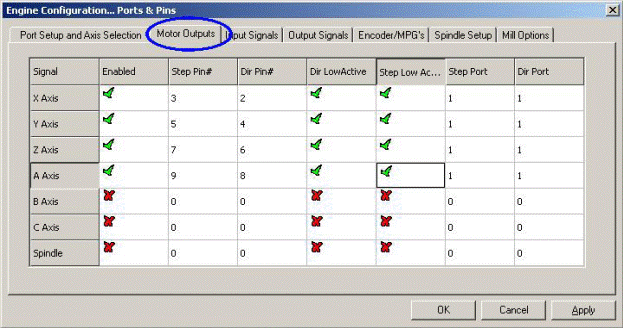
Рисунок 5.4 – Определяем подключения для осей и управляемого шпинделя
If your spindle speed will be controlled by Mach3 then you need to Enable the spindle and
allocated a Step pin/port for it if it uses pulse width modulated control with relays to control
its direction or to allocate Step and Direction pins/ports if it has full control. You should
also define if these signals are active-lo. When done, click the Apply button to save the
data on this tab.
5.3.2 Input signals to be used
Now select the Input Signals tab. This will look like figure 5.5.
We assume that you have chosen one of the home/limit strategies from chapter 4.6.
If you have used strategy one and the limit switches are connected together and trigger an
EStop or disable the axis drives via the drive electronics then you do not check any of the
Limit inputs.
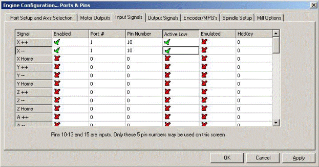
Figure 5.5 – Input signals
With strategy two you will probably have home switches on the X, Y and Z axes. Enable
the Home switches boxes for these axes and define the Port/Pin to which each is connected.
If you are combining limits and the home switch then you should enable the Limit --, the
Limit ++ and Home for each axis and allocate the same pin to Home, Limit— and Limit++.
Notice the scroll bar to access the rest of the table which is not visible in figure 5.5.
The Input #1 is special in that it can be used to inhibit running a part program when safety
guards are not in place. The other three (and #1 if not used for the guard interlock) are
available for your own use and can be tested in the code of macros. The Input #4 can be
used to connect an external pushbutton switch to implement the Single Step function. You
may wish to configure them later.
Enable and define Index Pulse if you have a spindle sensor with just one slot or mark.
Enable and define Limits Override if you are letting Mach2 control your limit switches and
you have an external button which you will press when you need to jog off a limit. If you
have no switch then you can use a screen button to achieve the same function.
Enable and define EStop to indicate to Mach3 that the user has demanded an emergency
stop.
Enable and define OEM Trigger inputs if you want electrical signals to be able to call OEM
button functions without a screen button needing to be provided.
Enable and define Timing if you have a spindle sensor with more than one slot or mark.
Enable Probe for digitising and THCOn, THCUp and THCDown for control of a Plasma
torch.
If you have one parallel port then you have 5 available inputs; with two ports there are 10
(or with pins 2 to 9 defined as inputs, 13). It is very common to find that you are short of
input signals especially if you are also going to have some inputs for glass scales or other
encoders. You may have to compromise by not having things like a physical Limit Override
switch to save signals!
You can also consider using a Keyboard Emulator for some input signals.
Click the Apply button to save the data on this tab.
5.3.3 Emulated input signals
If you check the Emulated column for an input then the Port/Pin number and active-lo state
for that signal will be ignored but the entry in the Hotkey column will be interpreted. When
a key-down message is received with code that matches a Hotkey value then that signal is
considered to be active. When a key-up message is received then it is inactive.
The key-up and key-down signals usually come from a keyboard emulator (like the
Ultimarc IPAC or Hagstrom) which is triggered by switches connected to its inputs. This
allows more switches to be sensed than spare pins on your parallel ports but there may be
significant time delays before the switch change is seen and indeed a key-up or key-down
message can get lost by Windows.
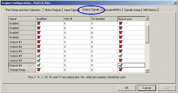
Figure 5.6 – Output signals
Emulated signals cannot be used for Index or Timing and should not be used for EStop.
5.3.4 Output Signals
Use the Output signals tab to define the outputs you require. See figure 5.6.
You will probably only want to use one Enable output (as all the axis drives can be
connected to it). Indeed if you are using the charge pump/pulse monitor feature then you
may enable your axis drives from its output.
The Output# signals are for use to control a stop/start spindle (clockwise and optionally
counterclockwise), the Flood and Mist coolant pumps or valves and for control by your own
customized Mach3 buttons or macros.
The Charge Pump line should be enabled and defined if your breakout board accept this
pulse input to continually confirm correct operation of Mach3. Charge Pump2 is used if
you have a second breakout board connected to the second port or want to verify the
operation of the second port itself.
Click the Apply button to save the data on this tab.
5.3.5 Defining encoder inputs
The Encoder/MPGs tab is used to define the connections and the resolution of linear
encoders or Manual Pulse Generators (MPGs) used for jogging the axes.
The Encoder/MPGs tab is used to define the connections and the resolution of linear
encoders or Manual Pulse Generators (MPGs) used for jogging the axes. It is covered here
for completeness of the description of Config> Ports & Pins.
This dialog does not need an active-lo column as, if the encoders count the wrong way it is
merely necessary to swap the pins allocated for A and B inputs.
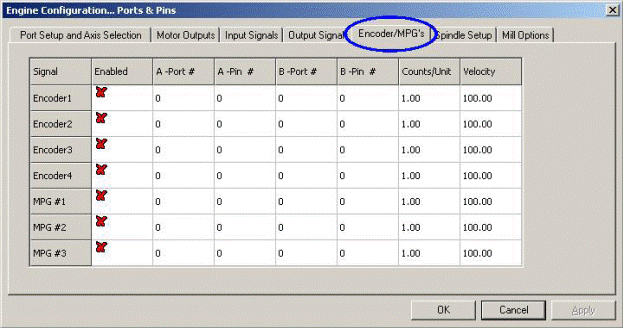
Figure 5.7 – Encoder inputs
5.3.5.1 Encoders
The Counts per unit value should be set to correspond to the resolution of the encoder. Thus
a linear scale with rulings at 20 microns produces a count every 5 microns (remember the
quadrature signal), that is 200 counts per unit (millimetre). If you have Native units set as
inches the it would be 200 x 25.4 = 5080 counts per unit (inch). The Velocity value is not
used.
5.3.5.2 MPGs
The Counts per unit value is used to define the number of quadrature counts that need to be
generated for Mach3 to see movement of the MPG. For a 100 CPR encoder, a figure of 2 is
suitable. For higher resolutions you should increase this figure to get the mechanical
sensitivity you want. We find 100 works well with 1024 CPR encoders.
The Velocity value determines the scaling of pulses sent to the axis being controlled by the
MPG. The lower the value given in Velocity the faster the axis will move. Its value is best
set by experiment to give a comfortable speed when spinning the MPG as fast as is
comfortable.
5.3.6 Configuring the spindle
The next tab on Config> Ports & Pins is Spindle Setup. This is used to define the way in
which your spindle and coolant is to be controlled. You may opt to allow Mach3 to do
nothing with it, to turn the spindle on and off or to have total control of its speed by using a
Pulse Width Modulated (PWM) signal or a step and direction signal. The dialog is shown in
figure 5.8.
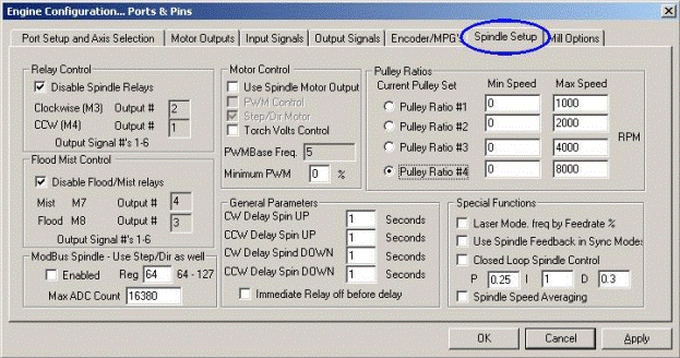
Figure 5.8 – Spindle Setup
5.3.6.1 Coolant control
Code M7 can turn Flood coolant on, M9 can turn Mist coolant on and M9 can turn all
coolant off. The Flood Mist control section of the dialog defines which of the output signals
are to be used to implement these functions. The Port/Pins for the outputs have already been
defined on the Output Signals tab.
If you do not want to use this function check Disable Flood/Mist Relays.
5.3.6.2 Spindle relay control
If the spindle speed is controlled by hand or by using a PWM signal then Mach3 can define
its direction and when to start and stop it (in response to M3, M4 and M5) by using two
outputs. The Port/Pins for the outputs have already been defined on the Output Signals tab.
If you control the spindle by Step and Direction then you do not need these controls. M3,
M4 and M5 will control the pulse train generated automatically.
If you do not want to use this function check Disable Spindle Relays.
5.3.6.3 Motor Control
Check Use Motor Control if you want to use PWM or Step and Direction control of the
spindle. When this is checked then you can choose between PWM Control and Step/Dir
Motor.
|
|