Главная страница Случайная страница
Разделы сайта
АвтомобилиАстрономияБиологияГеографияДом и садДругие языкиДругоеИнформатикаИсторияКультураЛитератураЛогикаМатематикаМедицинаМеталлургияМеханикаОбразованиеОхрана трудаПедагогикаПолитикаПравоПсихологияРелигияРиторикаСоциологияСпортСтроительствоТехнологияТуризмФизикаФилософияФинансыХимияЧерчениеЭкологияЭкономикаЭлектроника
Steering
|
|
Table of Contents
Exploded View................................................................................................................................ 13-2
Specifications................................................................................................................................. 13-3
Steering............................................................................................................................................. 13-4
Steering Inspection.................................................................................................................. 13-4
Steering Adjustment................................................................................................................ 13-4
Steering Stem................................................................................................................................. 13-5
Stem, Stem Bearing Removal............................................................................................... 13-5
Stem, Stem Bearing Installation........................................................................................... 13-5
Stem Bearing Lubrication....................................................................................................... 13-7
Handlebar......................................................................................................................................... 13-8
Handlebar Removal.................................................................................................................. 13-8
Handlebar Installation.............................................................................................................. 13-8

AD: Apply adhesive. G: Apply grease.
| Exploded View |
L Apply a non-permanent locking agent. T1: 39 N-m (4.0 kg-m, 29 ft-lb) T2: 4.9 N-m (0.50 kg-m, 43 in-lb)
or Hand-tight T3: 6.9 N-m (0.70 kg-m, 61 in-lb) T4: 34 N-m (3.5 kg-m, 25 ft-lb)
T5: 23 N-m (2.3 kg-m, 16.5 ft-lb) T6: 9.8 N-m (1.0 kg-m, 87 in-lb) T7: 3.4 N-m (0.35 kg-m, 30 in-lb) T8: 21 N-m (2.1 kg-m, 15.0 ft-lb) T9: 28 N-m (2.9 kg-m, 21 ft-lb)
____________________________________________________________________________ STEERING 13-3
Specifications
Special Toole - Steering Stem Nut Wrench: 57001-1100
Head Pipe Outer Race Press Shaft 57001-1075 Head Pipe Outer Race Drivers: 57001-1077 (2) Steering Stem Bearing Driver 57001-1344 Steering Stem Bearing Driver Adapter 57001-1345
Steering
Steering Inspection •Check the steering.
О Lift the front wheel off the ground using the jack. Special Tool - Jack: 57001-1238
О With the front wheel pointing straight ahead, alternately tap each end of the handlebar. The front wheel should swing fully left and right from the force of gravity until the fork hits the stop. *lf the wheel binds or catches before the stop, the steering is too tight. О Feel for steering looseness by pushing and pulling the forks. *lf you feel looseness, the steering is too loose.
NOTE
|
О The cables and wiring will have some effect on the motion of the fork which must be taken into account Be sure the wires and cables are properly routed. О The bearings must be in good condition and properly lubricated in order for any test to be valid.
Steering Adjustment • Remove:
Upper fairing (see Frame chapter)
Fuel Tank (see Fuel System chapter)
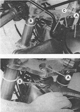
Air Cleaner Housing [A] (see Fuel System chapter)
| L |
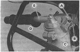
Rear View Mirror Bracket [B] and Mounting Bolts [C]
• Loosen:
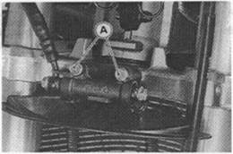
Lower Fork Clamp Bolts (both sides) Stem Head Nut [A] •Adjust the steering.
Special Tool - Steering Stem Nut Wrench: 57001-1100 [B]
*lf the steering is too tight loosen the stem nut a fraction of a turn. *lf the steering is too loose, tighten the nut a fraction of a turn.
NOTE
О Turn the stem nut 1/8 turn at a time maximum.
•Tighten the steering stem head nut and lower fork clamp bolts.
Torque - Steering Stem Head Nut: 39 N-m(4.0 kg-m, 29 ft-lb)
Front Fork Clamp Bolts (Lower): 28 N-m (2.9 kg-m, 21 ft-lb)
• Check the steering again.
*lf the steering is still too tight or too loose, repeat the adjustment.
Stem, Stem Bearing Removal
• Remove:
Upper and lower Fairings (see Frame chapter) Fuel Tank (see Fuel System chapter) Air Cleaner Housing (see Fuel System chapter) Rear View Mirror Bracket Brake Hose Joint Mounting Bolts [A] Front Wheel (see Wheels/Tires chapter) Front Fork (see Suspension chapter) Steering Stem Head Nut and Washer Steering Stem Head
• Pushing up the stem base, and remove the lock washer [A], stem nut [B], stem cap [C] and O-ring, then remove the steering stem [D] and stem base.
Special Tool - Stewing Stem Nut Wrench: 57001-1100

|
• Remove the upper stem bearing inner race.
•To remove the outer races [A] pressed into the head pipe [B], insert a bar [C] into the head pipe, and hammer evenly around the circumference of the opposite race to drive it out
NOTE

|
О If either steering stem bearing is damaged, it is recommended that both the upper and lower bearings (including outer races) should be replaced with new ones.
• Remove the lower stem bearing (with its grease seal) which is pressed onto the steering stem with a suitable commercially available bearing puller.
Stem, Stem Bearing Installation
•Apply grease to the outer races, and drive them into the head pipe at the same time.
|
|
| ____________________________________________________________________________ STEERING 13-5 Steering Stem |
Special Tools - Head Pipe Outer Race Press Shaft: 57001-1075 [A] Head Pipe Outer Race Drivers: 57001-1077 [B] (2)
•Apply grease to the lower inner race [A], and drive it onto the stem.
Special Tools - Steering Stem Bearing Driver 57001-1344 [B]
Steering Stem Bearing Driver Adapter. 57001-1345
[C]
•Apply grease to the upper inner race, and install it in the head pipe.
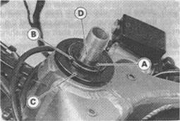
• Install the stem through the head pipe and the upper inner race, and install the O-ring on the stem shaft while pushing up on the stem base [А].
• Install the stem cap [B], and hand tighten the stem nut [С].
NOTE
|
О Install the steering stem nut so that the stepped side [D] faces down.
• Install the stem head.
•Install the washer, and tighten the stem head nut lightly. •Settle the inner races in place as follows:
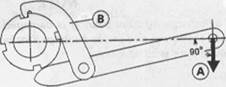
OTighten the stem nut to 39 N-m (4.0 kg-m, 29 ft-lb) of torque. (To tighten the steering stem nut to the specified torque, hook the wrench on the stem nut and pull the wrench at the hole by 22.2 kg [A] force in the direction shown.)
Special Tool - Steering Stem Nut Wrench: 57001-1100 [B]
О Check that there is no play and the steering stem turns smoothly without rattles. If not the bearings on the inner races may be damaged.
OAgain back out the stem nut a fraction of a turn until it turns lightly. •Turn the stem nut lightly clockwise until it just becomes hard to turn. Do not overtighten, or the steering will be too tight.
Torque - Steering Stem Nut Hand-tight or 4.9 N-m (0.50 kg-m, 43 In-lb)
•Install the front fork (see Suspension chapter).
NOTE
О Tighten the fork upper damp bolts first next the stem head nut last the fork lower damp bolts.
Torque - Steering Stem Head Nut: 39 N-m (4.0 kg-m, 29 ft-lb)

Front Fork Clamp Bolts (Upper): 21 N-m (2.1 kg-m, 15 It-lb) (Lower): 28 N-m (2.9 kg-m, 21 ft-lb)
• Install the removed parts (see appropriate chapters).
AWARNING
Do not Impede the handlebar turning by routing the cables, harnesses and hoses Improperly (see General Information chapter).
Stem Bearing Lubrication
• Remove the steering stem.
• Using a high flash-point solvent, wash the upper and lower tapered roller bearings in the cages, and wipe the upper and lower outer races, which are press-fitted into the frame head pipe, clean off grease and dirt.
•Visually check the outer races and the rollers.
• Replace the bearing assemblies if they show wear or damage.
• Pack the upper and lower tapered roller bearings [A] in the cages with grease, and apply a light coat of grease to the upper and lower outer races.

|
• Install the steering stem, and adjust the steering.
Handlebar
Handlebar Removal
• Remove:
Clutch Master Cylinder Left Handlebar Switch Housing Front Brake Master Cylinder Right Handlebar Switch Housing Throttle Grip Handlebar Bolts [A] Handlebar Holder Position Bolts [B] Handlebar Holder Bolts [C]
• Remove the handlebar holder [D] from the front fork, and then pull out the handlebar [Е].
Handlebar Installation
•Apply a non-permanent locking agent to the threads of handlebar holder position bolts and handlebar bolts, and tighten the following bolts.
Torque - Handlebar Holder Bolts: 23 N-m (2.3 kg-m, 16.5 ft-lb)
Handlebar Holder Position Bolts: 9.8 N-m (1.0 kg-m, 87 In-lb) Handlebar Bolts: 34 N-m (3.5 kg-m, 25 ft-lb)
|

|
•Install the removed parts (see appropriate chapters).
Frame
Table of Contents
Exploded View................................................................................................................................. 14-2
Seats.................................................................................................................................................. 14-5
Rear Seat Removal................................................................................................................... 14-5
Rear Seat Installation............................................................................................................... 14-5
Front Seat Removal.................................................................................................................. 14-5
Front Seat Installation.............................................................................................................. 14-5
Side Covers...................................................................................................................................... 14-6
Side Cover Removal................................................................................................................. 14-6
Fairings.............................................................................................................................................. 14-7
Inner Fairing Removal.............................................................................................................. 14-7
Inner Fairing Installation.......................................................................................................... 14-7
Upper Fairing Removal............................................................................................................ 14-7
Lower Fairing Removal............................................................................................................ 14-7
Fenders............................................................................................................................................. 14-8
Front Fender Removal............................................................................................................. 14-8
Rear Fender Removal.............................................................................................................. 14-8
Rear Frame....................................................................................................................................... 14-9
Rear Frame Removal............................................................................................................... 14-9
Rear Frame Installation........................................................................................................... 14-9
| Exploded View |

L Apply a non-permanent
locking agent. 0: Apply oil.
(ZX900-B3 other than US. CN)
(ZX900-B3 other than US, CN)
T1: 44 N-m (4.5 kg-m, 33 ft-lb) T2: 34 N-m (3.5 kg-m, 25 ft-l>) T3: 49 N-m (5.0 kg-m. 36 ft-lb)

|

|

|
AR: Austria CN: Canada FG: Germany GR: Greek NR: Norway SD: Sweden ST: Switzerland US: United States
Seats__________________________________________________
Rear Seat Removal
• Insert the ignition switch key into the seat lock [A], turning the key counterclockwise, pulling up on the rear of the seat [B], and pulling the seat forward.
Rear Seat Installation
•Slip the rear loop [A] under the hooks [B] on the hook bracket [С].
• Insert the seat pin [D] into the latch hole [Е].

• Push down the rear part of the seat until the lock clicks.
Front Seat Removal
• Remove:
Rear Seat
Bolts [A] and Hook Bracket [B]
• Remove the front seat [C] by pulling it up on the rear and to the rear.
Front Seat Installation

•Slip the front seat hook [A] under the brace [B] on the fuel tank bracket [C], and insert the seat pins [D] into the holes [E] in the frame.
Side Covers
Side Cover Removal • Remove: Seats
Bolts [A] (ZX900-B3 other than US, CN)
Passenger Grab Rail [B] (ZX900-B3 other than US, CN)
Screws (A] Clamps [B]
Tail/Brake Lights Lead Connector • Pull the left and right side covers with the tail/brake lights backward.
• Remove:

Tail/Brake Lights Bracket [A] and Bolts [B] Screws [C]
Left Side Cover, Right Side Cover and Rear Center Cover [D]
>
Fairings
Inner Fairing Removal
• Remove the screws [A], and pull the front part of the inner fairing [B] upward [C] to clear the stopper
• Remove the inner fairing.
• Remove the other inner fairing in the same manner.
Inner Fairing Installation
• Fit the projection [A] on the inner fairing [B] into the hole [C] in the air intake duct [D].

|
• Install the screws.
Upper Fairing Removal
• Remove:
Inner Fairing
Rear View Mirrors [A]
Bracket Nuts [B]
Screws [C]
Headlight Connector
Turn Signal Light Lead Connectors
City Light Connector (other than US, Canada and Australia)
• Remove the upper fairing.
Lower Fairing Removal
• Remove:
Screws [A] [B] Allen Bolts [C] Clamp [D]
• Pull the lower front part of the lower fairing outward to clear the stoppers [Е].
• Remove the lower fairing.
• Remove the other lower fairing in the same manner.
NOTE

О If when the left and right lower fairings removed at the same time, do not remove the screws [В] (both sides), damp [D] and stoppers
Fenders
Front Fender Removal
• Remove the screws [A] and take off the front fender front [В].
• Remove:
Brake Hose Clamps [A] Speedometer Cable Clamp [B] Bolts [C]
• Remove the front fender rear [D].
Rear Fender Removal
• Remove:
Seats
Side Covers Junction Box
Starter Relay and Main Fuse Turn Signal Relay Fuel Pump Relay Battery
Rear Brake Reservoir Mounting Bolt Turn Signal Light Lead Connectors Gas Reservoir Hooks [A] Bolt [B]

• Remove the rear fender [С].
Rear Frame
Rear Frame Removal • Remove: Seats
Side Covers Junction Box
Starter Relay and Main Fuse Turn Signal Relay Fuel Pump Relay Battery
Rear Brake Reservoir Mounting Bolt 1С Igniter

|
Turn Signal Light Lead Connector Gas Reservoir Rear Footpeg Bracket [A] Frame Bolts and Nuts [B]
Rear Frame Installation •Tighten the frame bolts and nuts.
Torque - Rear Frame Bolts and Nuts: 44 N-m (4.5 kg-m, 33 fl-lb)
|
|