Главная страница Случайная страница
Разделы сайта
АвтомобилиАстрономияБиологияГеографияДом и садДругие языкиДругоеИнформатикаИсторияКультураЛитератураЛогикаМатематикаМедицинаМеталлургияМеханикаОбразованиеОхрана трудаПедагогикаПолитикаПравоПсихологияРелигияРиторикаСоциологияСпортСтроительствоТехнологияТуризмФизикаФилософияФинансыХимияЧерчениеЭкологияЭкономикаЭлектроника
Read the text. The purpose of the railfastenings isto maintain the track gauge and to transmit forces acting on and in the rails to the sleepers
|
|
The purpose of the rail fastenings isto maintain the track gauge and to transmit forces acting on and in the rails to the sleepers. In other words, fastenings are used:
1) to connect rails together (joint fastenings);
2) to tie the rails to the sleepers (intermediate fastenings);
3) to restrict longitudinal movement of rails relative to the sleepers (anti-creep devices).
1) In the case of joint fastenings, Russian railways use two types of joints: conventional and insulated.
At a conventional joint (Figure 5.1) two fishplates with fish bolts, spring washers and nuts are used. The joint is between two sleepers.

|
| Figure 5.1 |
Insulated joints (Figure 5.2) with insulated fishplates are applied in track circuited areas to prevent the current leakage between sections of rail.

|
| Figure 5.2 |
2) Intermediate fastenings (with baseplates) can be categorized as follows:
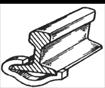
a) direct fastenings (Figure 5.3)
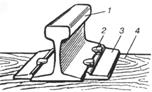  KN-65
(1 – rail; 2 – spike; 3 – base plate; 4 – sleeper; 5 – clip; 6 – bolt) KN-65
(1 – rail; 2 – spike; 3 – base plate; 4 – sleeper; 5 – clip; 6 – bolt)
|
| Figure 5.3 |
b) mixed fastenings (Figure 5.4)
 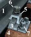 KD
(1 – rail; 2 – spike; 3 – base plate; 4 – sleeper; 5 – clip; 6 – bolt; 7 - screw) KD
(1 – rail; 2 – spike; 3 – base plate; 4 – sleeper; 5 – clip; 6 – bolt; 7 - screw)
|
| Figure 5.4 |
c) indirect fastenings (Figure 5.5)
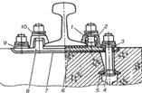  KB-65
(1 – clip bolt; 2 – clip; 3 – insulating bush; 4 – T-headed bolt; 5 – anchor washer; 6 –rail pad; 7 – ribbed sole plate; 8 – steel plate; 9 – flat washer; 10 – spring double-screw washer) KB-65
(1 – clip bolt; 2 – clip; 3 – insulating bush; 4 – T-headed bolt; 5 – anchor washer; 6 –rail pad; 7 – ribbed sole plate; 8 – steel plate; 9 – flat washer; 10 – spring double-screw washer)
|
| Figure 5.5 |
Intermediate fastenings (without baseplates) can be defined as follows:
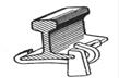
a) anchor fastenings (Figure 5.6)
 ARS-4 ARS-4  Pandrol-350 Pandrol-350
|
| Figure 5.6 |
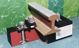
b) bolted fastenings (Figure 5.7) c) tension clamp fastenings (Figure 5.8)
 ZhBR-65 ZhBR-65
|
| Figure 5.7 |
 W-30 W-30
|
| Figure 5.8 |
3) To restrict longitudinal movement of rails relative to sleepers anti-creep devices are used. The most typical of them are:
a) spring anchor (Figure 5.9) b) wedge anchor (Figure 5.10)
|
| Figure 5.9 |
|
| Figure 5.10 |
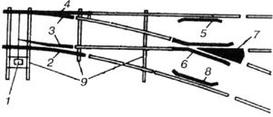
Turnouts (switches) are of special importance for railways, as they are the prerequisite for the development of networks, i.e. for the branching and joining of tracks. The productivity and line speed of a railway is essentially influenced by the number and type of its turnouts. The structure of a turnout is far more complicated and expensive than that of the track grid. Turnoutsenable vehicles to pass from one track to another without interrupting their run.
A standard turnout (Figure 5.11) consists of point machine (1), stock rails (2, 4), point blades (3), check rails (5, 8), wing rail (6), point of crossing (7), crossing sleepers (9). (Figure 5.11) In standard or single turnoutsa distinction is made between right-hand and left-hand (Figure 5.12) turnouts depending on the direction the diverging track takes.
|
| Figure 5.11 |
In standard or single turnoutsa distinction is made between right-hand and left-hand (Figure 5.12) turnouts depending on the direction the diverging track takes.
|
| Figure 5.12 |
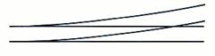
A symmetrical turnout (Figure 5.13) is a special case of turnout with two routes diverging symmetrically from the common route.

|
| Figure 5.13 |
Diamond crossing with a single slip(Figure 5.14) has one connection between intersecting routes and because of this has three routing possibilities.
|
| Figure 5.14 |
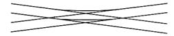
Diamond crossing with double slips (Figure 5.15) consists of twodiagonally intersecting tracks which are connected by two curves. This means there are four routing possibilities.

|
| Figure 5.15 |
When two tracks intersect at the same level they form a crossing where the direction of the vehicles cannot be changed. The most commonly used types of diamond crossings are right-angle crossings (Figure 5.16) and oblique crossings (Figure 5.17).
|
| Figure 5.16 |
|
| Figure 5.17 |

|
|