Главная страница Случайная страница
Разделы сайта
АвтомобилиАстрономияБиологияГеографияДом и садДругие языкиДругоеИнформатикаИсторияКультураЛитератураЛогикаМатематикаМедицинаМеталлургияМеханикаОбразованиеОхрана трудаПедагогикаПолитикаПравоПсихологияРелигияРиторикаСоциологияСпортСтроительствоТехнологияТуризмФизикаФилософияФинансыХимияЧерчениеЭкологияЭкономикаЭлектроника
Electrical System
|
|
Table of Contents
Parts Location.................................................................. 15-2
Exploded View................................................................. 15-3
Specifications.................................................................. 15-6
ZX900-B1, B2 Wiring Diagram (US and Canada) 15-7
ZX900-B1, B2 Wiring Diagram (Australia)...................... 15-8
ZX900-B1, B2 Wiring Diagram
(United Kingdom)............................................................. 15-9
ZX900-B1, B2 Wiring Diagram
(European Models except United Kingdom)................. 15-10
Precautions.................................................................... 15-11
Electrical Wiring............................................................ 15-12
Wiring Inspection..................................................... 15-12
Battery............................................................................ 15-13
Charging Condition Inspection................................ 15-13
Refreshing Charge................................................... 15-13
Alternator........................................................................ 15-15
Removal................................................................... 15-15
Installation................................................................ 15-15
Disassembly............................................................ 15-15
Assembly................................................................. 15-17
Operational Inspection............................................ 15-19
Test No. 1 -Battery Discharged.......................... 15-19
Test No. 2-Battery Overcharged......................... 15-20
Test No. 3-Noise................................................. 15-20
Stator Coil Inspection.............................................. 15-20
Rotor Coil Inspection............................................... 15-21
Slip Ring Cleaning................................................... 15-21
Slip Ring Diameter................................................... 15-22
Carbon Brush Length............................................... 15-22
Rectifier Inspection.................................................. 15-22
Regulator Inspection................................................ 15-22
Alternator Ball Bearing Inspection........................... 15-23
Ignition System............................................................. 15-24
Pickup Coil Removal............................................... 15-25
Pickup Coil Installation............................................ 15-25
Pickup Coil Inspection............................................. 15-26
Ignition Coil Removal/Installation........................... 15-26
Ignition Coil Inspection............................................ 15-26
Spark Plug Removal................................................ 15-27
Spark Plug Installation............................................. 15-28
Spark Plug Gap Inspection...................................... 15-28
1С Igniter Inspection................................................ 15-28
Starter Motor.................................................................. 15-31
Removal................................................................... 15-31
Installation................................................................ 15-31
Disassembly............................................................ 15-31
Assembly................................................................ 15-32
Brush Inspection..................................................... 15-33
Commutator Cleaning and Inspection.................... 15-33
Armature Inspection................................................ 15-33
Brush Lead Inspection............................................ 15-34
Brush Plate and Terminal Bolt Inspection.............. 15-34
Starter Relay Inspection......................................... 15-34
Lighting System..........................,............................... 15-36
Headlight Beam Horizontal Adjustment................. 15-36
Headlight Beam Vertical Adjustment...................... 15-36
Headlight Bulb Replacement.................................. 15-37
Headlight Diode Inspection
(Europe models except U.K.)................................. 15-37
Tail/Brake Light Bulb Replacement........................ 15-40
License Plate Light Bulb Replacement.................. 15-40
Turn Signal Relay Inspection................................. 15-40
Fuel Pump..................... 1............................................ 15-43
Removal/Installation............................................... 15-43
Fuel Pump Relay Inspection.................................. 15-43
Fuel Pump Operational Inspection......................... 15-43
Radiator Fan System................................................... 15-45
Fan System Circuit Inspection............................... 15-45
Fan Motor Inspection.............................................. 15-45
Meters, Gauges........................................................... 15-46
Removal.................................................................. 15-46
Meter, Gauge Disassembly.................................... 15-46
Bulb Replacement................................................... 15-46
Meter, Gauge Assembly......................................... 15-46
Tachometer Inspection........................................... 15-47
Water Temperature Gauge Inspection................... 15-48
Fuel Gauge Operation Inspection.......................... 15-49
Switches and Sensors................................................. 15-50
Front Brake Light Switch Inspection...................... 15-50
Rear Brake Light Switch Adjustment...................... 15-50
Radiator Fan Switch Inspection............................. 15-50
Water Temperature Sensor Inspection.................. 15-51
Fuel Level Sensor Inspection................................. 15-51
Junction Box................................................................ 15-52
Junction Box Fuse Circuit Inspection.................... 15-52
Starter Circuit/Headlight Relay Inspection............ 15-52
Diode Circuit Inspection......................................... 15-53
Fuse............................................................................. 15-55
30A Main Fuse Removal........................................ 15-55
Junction Box Fuse Removal.................................. 15-55
Fuse Installation..................................................... 15-55
Fuse Inspection...................................................... 15-55
Parts Location

|

|
1. Ignition Coils
2. Alternator
3. Starter Motor
4. Fuel Pump
5. Fuel Pump Relay
6. Junction Box
7. Starter Lockout Switch
8. Radiator Fan Switch
9. Neutral Switch
10. Side Stand Switch
11. Turn Signal Relay
12. Starter Relay and Main Fuse
13. 1С Igniter
14. Rear Brake Light Switch
15. Front Brake Light Switch
16. Water Temperature Sensor
17. Pickup Coil
18. Oil Pressure Switch

1. City Light (Except AS, CN, US)
2. Headlight (AS, CN, UK, US)
3. Headlights (Europe except UK)
4. Turn Signal Lights
5. Pickup Coil
6. 1С Igniter
7. Tail/Brake Lights
8. License Light
AS: Australia IT: Italy
L: Apply a non permanent locking agent.
T1: 13 N-m (1.3 kg-m, 113 in-lb)
T2: 9.8 N-m (1.0 kg-m, 87 in-lb)
T3: 7.8 N-m (0.80 kg-m, 69 in-lb)
T4: 25 N-m (2.5 kg-m, 18.0 ft-lb)
| Exploded View |
T5: 1.0 N-m (0.10 kg-m, 9 in-lb)
1. Fuel Pump Relay
2. Fuel Pump
3. Starter Motor Clutch
4. Starter Relay
EO: Apply engine oil.
L Apply a non-permanent locking agent. M: Apply molybdenum disulfide grease.

|
T1: 25 N-m (2.5 kg-m, 18.0 ft-lb) T2: 54 N-m (5.5 kg-m, 40 ft-lb) T3: 4.4 N-m, (0.45 kg-m, 39 in-lb) T4: 2.5 N-m (0.25 kg-m, 22 in-lb) T5: 3.4 N-m (0.35 kg-m, 30 in-lb)
T6: 11 N-m (1.1 kg-m, 95 in-lb) T7: 4.9 N-m (0.50 kg-m, 43 in-lb) T8: 5.9 N-m (0.60 kg-m, 52 in-lb) T9: 9.8 N-m (1.0 kg-m, 87 in-lb) T10: 12 N-m (1.2 kg-m, 104 in-lb)

|
L Apply a non-permanent locking agent.
SS: Apply silicone sealant.
Tl: 3.4 N-m (0.35 kg-m, 30 in-lb)
T2: 18 N-m (1.8 kg-m, 13.0 ft-lb)
T3: 7.8 N-m (0.80 kg-m, 69 in-lb)
T4: 15 N-m (1.5 kg-m. 11.0 ft-lb)
| 4. Radiator Fan Switch 5. Water Temperature Sensor 6. Radiator Fan 7. Oil Pressure Switch 8. Neutral Switch 9. Front Brake Light Switch 10. Ignition Switch 11. Side Stand Switch 12. Starter Lockout Switch 13. Rear Brake Light Switch |
T5: 1.0 N-m (0.10 kg-m, 9 in-lb)
Specifications
| Item | Standard |
| Battery: Type Capacity Voltage | MF (Maintenance Free) Battery 12 V 10 Ah 12.6 V or more |
| Alternator (Charging System): Type Charging voltage Rotor coil resistance Stator coil resistance Slip ring diameter Carbon brush length | Three-phase AC (built-in regulator/rectifier) 14.2 ~ 14.8 V @ engine speed 4 000 r/min(rpm) 2.3 - 3.5 О 1.0 Q or less 14.4 mm (Service Limit 14.0 mm) 10.5 mm (Service Limit 4.5 mm) |
| Ignition System: Pickup coil air gap Pickup coil resistance Ignition coil: 3 needle arcing distance Primary winding resistance Secondary winding resistance Spark plug: Spark plug gap Spark plug cap resistance 1С igniter resistance | 0.4 ~ 0.6 mm (Non-adjustable) 375 ~ 565 О (x 100 О) 7 mm or more 2.3 ~ 3.5 Q (x 1 O) 12 ~ 18 kQ (x 1 kO) 0.7 - 0.8 mm (Twin - electrode Spark Plug) 3.75 ~ 6.25 kQ (x 1 kQ) in the text |
| Electric Starter System: Starter motor: Brush length Commutator diameter | 12 mm (Service limit 8.5 mm) 28 mm (Service limit 27 mm) |
| Fuel Pump: Fuel pump relay internal resistance Fuel pump pressure | in the text 11 - 16 kPa (0.11 ~ 0.16 kg/cm2, 1.6 ~ 2.3 psi) |
| Switch and Sensor: Rear brake light switch timing Engine oil pressure switch connections Fan switch connections Rising temperature Falling temperature Water temperature sensor resistance Fuel level sensor resistance | ON after about 10 mm pedal travel When engine is stopped: ON When engine is running: OFF From OFF to ON @ 93 - 103'C (199 ~ 217'F) From ON to OFF @ 91 ~ 95eC (196 - 203'F) ON: Less than 0.5 О OFF: More than 1 MQ 47 ~ 57 Q @80*C (176*F) 25 ~ 30 0@100'C (212'F) FULL position: 1 EMPTY position: 103 ~117 Q |
| Special Tools - Hand Tester: 57001-983 Crankcase Splitting Tool Assembly: 57001-1362 Bearing Driver Set 57001-1129 Spark Plug Wrench, 16mm: 92110-1154 |
Sealant - Kawasaki Bond (Silicone Sealant): 56019-120
ZX900-B1, В2, ВЗ Wiring Diagram (US and Canada)

| Radiator Fan switch |
| Right Handlebar switches 1. Front Brake Light Switch 2. Engine stop switch 3. starter Button |
| spark t |
| Neutral indicator Light 12V3.4W Tachometer Light 12V1. 7WX2 |
| Speedometer Light 12V1. 7WX2 |
| water Temperature Gauge |
| ignition Switch |
| Tachometer |
| Fuel Gauge |
| water Temp/Fuel Gauge Light 12V1. tv High Bean indicator Light 12V3.4W Turn signal indicator Light 12V3.4W 011 Pressure warnIng LlQht 12V3.4W |
| Headiight 12V60/55W |
| ж mm I I | -a |T | |
| L-L | ||
| t-f iL -LJ i | INI |
| Ф ® ® < D |
| side stand switch |
| Horn 12V2.5A |
| ®b |
| Left Handlebar Switches 1. Horn Button 2. Turn signal Switch 3. Dimmer switch 4. starter Lockout switch |
| Front Right Turn signal Light 12V23V |
| СГ -WU— СГ - |
| Front Left Turn signal Light 12V23W |
| 6T -CCD— С - ll/Y-CO— K/Y- |
| OH |
| ir switch |
| H I Mi I fi, 11 ГГ.ГЛП1 |
| его |
| color»/Y IL |
| GY |
| LO |
| ClUtCft LMir |
| I ti < ■ £ |
| Ш |
| meued puiim in |
| HI |
та«М'1И7Л; «; ДНЖФЕШМИЕ
starter Lockout switch
Horn Button |Turn signal switch»ior I 'am imm«|
| 1М? 1к1ЫЖЧ711(4! В*]Т1*«1Г.ГЫ | |||||
| lonition | Bttttrr | lenition | ! lain I | Tall? I | |
| color | II | W | CT | BL | R |
| [" ОИ | aum | _____ | * |

| Turn Signal Relay |
| Junction Box 1. Horn Fuse 10A 2. ignition Fuse ЮА 3. те I I Iloht Fuse 10A 4. Headlight Fuse ioa 5. Fen Fuse IOA 6. ACC Fuse IOA 7. Turn signal Light Fuse IOA |
| Color code | |
| в к | Black |
| 8 L | Blue |
| В R | Brown |
| CH | chocolate |
| DC | Dark Green |
| С | Green |
| G Y | Gray |
| L В | LI ont Blue |
| L G | Light sreen |
| Orenge | |
| P | Pink |
| PU | purple |
| R | Red |
| W | white |
| r | Ye 11o* |
| 1 Front 8rale Lltfit $»ltch| | | mine stco aritcft j starter Button | | |||||
| color | BK BK | color | Ж | Rj color | Ш | |
| Irak* ie»er | OFF | push | mo | |||
| Pulled in | jutietMdi | |||||
| Released | RUN | -o I | ||||
| (98051 | -1402C)C |
ZX900-B1, B2, B3 Wiring Diagram (Australia)
| Rignt Handieoar switches 1. Front Brake Light Switch 2. Engine Stop Switch 3. Starter Button |

| Radiator Fan switch |
| span pij |
| Neutral indicator Light 12VJ.4W Tachometer Light 12V1.7WK2 |
| Speedometer Light 12V1.7WX2 |
| water Temperature eauge |
| Front Right Turn Signal Light 12V23W |
| Front Lert Turn signal Light 12V23W |
| ignition switch |
| Tachometer |
| Fuel Gauge |
| water Temp/Fuel Gauge Light 12V1. TV High Beam indicator Light 12V3. 4W Turn Signal indicator Light 12V3.4w oil Presaure warning Light 12V3. 4W |
| Headiignt I2V60/55W |
| ишлЕйжшыжашшкш 1MH llll I 1 111 INI li llllii | | |||||
| | Color 1 | br | ¥! | CT | BL | к |
| unm | |||||
| ON '(park) | _ |

| 2X900-83 Model |
| Turn signal Relay |
| I onlter |
| pickup Col I |
| Side Neutral stand switch Switch |
| У///////А Alternator |
| EAL: Electrleal Accessory Leads |
| on pressure switch |
| junction BOX 1.Horn FU88 10A 2.lonltlon Fuse 10A 3. Tall Iignt Fuse ioa 4. Headlight Fuse ioa 5. Fan Fuse ioa e.acc Fuse ioa т.Turn signal Light Fuse IOA |
| StSs-SfsS^ ftL, Till 1 I L Jill, -г ^ |
| Color Code | |
| в к | Black |
| В L | Blue |
| В R | Brown |
| CH | Chocolate |
| DG | Dark Green |
| б | Green |
| С Y | orav |
| L В | Light Blue |
| L С | Light Green |
| orange | |
| P | Pink |
| Pli | Purole |
| R | Red |
| W | white |
| T | re Ilo* |
шзшкш ш тлжшиж'ш *ша: и
| Front Br*e Llont | Wltcn | Engine sue aritcn | Starter Button | ||||
| color | BK | BK | Color | T/R R | Color | BK/R Ш/t | |
| eratt inn | orr | Push | |||||
| PullsO in | r*l*U4d | ||||||
| Reltaert | RUN | а—о | |||||
| («8051 | -1«50B)C |
ZX900-B1, В2, ВЗ Wiring Diagram (United Kingdom)

| Radiator Fan Switch |
| Neutral indicator Light 12VJ.4W Tachometer Light 12V1.7WX2 |
| water Temperature Gauge |
| Front Right Turn signal Light 12V21W |
| Horn I2V2.SA |
| Tachometer Speedometer Light 12V1. 7WX2 |
| city Light ^бЧТТ- Niviw |
| X3— 6Г • IC/T-OO—И/Т |
| ignition switch |
| Fuel Gauge |
| water Temp/Fuel Gauge Light 12V1.7W High Beam indicator Light 12V3.4W Turn signal indicator Light 12V3. 4W 011 Pressure warning Light 12V3.4W |
| Headlight 12V80/55W |
| Left Handlebar switches 1. Horn Button 2. Turn Signal Switch 3. Dimmer switch 4.Starter Lockout Switch 5.Passing Button |
| Front Left Turn signal Light 12V21W |

|
| s | |||||||||||
| Head! lght Switch | ! Front Brake Utfit 9»ltch | 1 Dwine stoc a»it£ ti | | i starter Button | ||||||||
| color | •All | BL | color | BK | •K | Color | VI | R | Color | ||
| err | OFF | Push | MO' I | ||||||||
| • | am | ■ Ю | ТТГТГ | H | |||||||
| ON | am | ■ 0 | RUN | от | ■ Ю | LZ | L=j |
| ($8051-1452B)С |

| ZX900-B3 Model |
| Turn signal Relay |
| Rear Right Turn signal ight 12V21V |
| cense Plate ght 12V5V |
| -Itiert Talll |
| Tel 12 |
| junction BOX 1.Horn Fuse IOA 2.ignition Fuse IOA 3. Tall light Fuse ioa 4. Headlight Fuse ioa 5. Fan Fuse IOA 8.ACC Fuse IOA 7.Turn Signal Light Fuse ioa |
| Color code | |
| BK | Black |
| В L | Blue |
| В R | Brown |
| CH | Chocolate |
| DC | Dart Green |
| с | Green |
| G Y | Gray |
| L В | Light Blue |
| LG | Light oreen |
| orange | |
| p | Pink |
| pu | Purple |
| r | Red |
| W | white |
| r | Ye 1 low |
| тзппяшЕСВ |
| 6Y bl |
ZX900-B1, B2, B3 Wiring Diagram (European Models except United Kingdom)
ignition Switch
Neutral indicator Light 12VJ.4W
| Radiator Fan switch |

|
| water Temo sensor ]№- Y/W- ©-II/Y- |
| dc dr= |
Tachometer Light 12V1.7Wx2
Right Handlebar swI tehee
1. Head Iight switch
2. Front Brake Light switch
3. Engine Stop Switch 4.Starter Button
Ф Ф Ф ®
| lS |
Г"
Г
SssfSss^;
| spark P ®|H> < J- ф|ч> о ф|ч> < - lonit о COI18 |

|
.мм
| Tachometer |
Radiator Fan
speedometer Light 12V1.7WX2
=1
water Temperature Gauge
Fuel Gauge
water Temp/Fuel Gauge Light 12V1.7W
| — 6Y — L—I |
| — 6Y |
| < n= |
High Beam indicator Light 12V3.4W Turn signal indicator Light 12V3.4W
oil Pressure warning Light 12V3.4W
City Light 12*51
| I oioda |

|
| Right Headlight (Low Seam) 12Y55W |
| " o |
| ! |
| (IT) |

|
| Left Headlight (High Beam) 12V55W |
| ! |
| Diode mm |
| ? side и stand ii switch |
(IT) S--5S* 5
l/IK-
■ H-H-N I I I I I I I I I I I Г
| —Jl 1 | Ш-i | ^ — | |
| -j | |||
| Ms | gJ | 1 1 1 |
® ® Ф ®
Horn I2V2.5A
| - с -CD— or -ll/Y-OO—1«л |
| (IT) |
Front Right Turn signal Light 12V21W
Left Handlebar switches
1. Horn Button
2. Turn Signal switch
3. Dimmer switch
4. starter Lockout Switch
| FG: wrw > I T: Ital lir I |
5. Passing Button
| Front Left Turn signal Light 12V21V |
| - e —OO— с ■ IK/Y-WD— ll/Y |
Horn 12V2.5A
| Horn Button color |> k/wik7y| со lor |
| r Switch m |
| Hi::: |
Turn signal switch! oir GY color
LO
Ш
HI
star tar Lockout Switch Paaalng Button color
inn
| ШОШШИЖШОВ'ШМ'К: |
Pulled in
| У |
| ii |
1ЕШЦ']Ж1УЛ1И1ЮШШ) ■ ИИОЕПЕШЕШПЕШК
GY IL
color r, LOCI он
lami
| color code | |
| Black | |
| Blue | |
| ВГ0МП | |
| chocolate | |
| I'lUl'lJUil | |
| ereen | |
| вга» | |
| Lieut Blue | |
| Light ereen | |
| Orange | |
| Pink | |
| purple | |
| Red | |
| white | |
| YellOW |
| starter Button color |вк/»|*Д |

| ZX900-B3 Mode I J. |
| Turn Signal Relay |
| |: Mrmn Model Italian Mod*; |
| junction BOX 1. Horn FUB6 10A 2. ignition Fuse 10A 3. Та 111 ight Fuse ЮА 4. HeadlIght Fuse 10A 6.Fan Fuse lOA 6. ACC Fuse IDA 7. Turn Signal Light Fuse 10A |
| сшзеваавдшвдЕвидшиаЕ |
| Щ-Ш |
| Headlight switch IL/Tj IL ■ /■ LlR/W |

| Frcnt Brake Light *lttt & я! п» stoc Mitch |
| OFF |
| huh |
| Push |
| TBI 12 В |
| Color |
| BK [ B> i |
| BK I BK: QMoc |
| Color |
| orr |
| eraka Later |
| Pulled in |
| Re I |
| («8051-14030. 1404C. 1431B)C |
Precautions
There are a number of important precautions that are musts when
servicing electrical systems. Learn and observe all the rules below.
О Do not reverse the battery lead connections. This will burn out the diodes on the electrical parts.
OAlways check battery condition before condemning other parts of an electrical system A fully charged battery is a must for conducting accurate electrical system tests.
OThe electrical parts should never be struck sharply, as with a hammer, or allowed to fall on a hard surface. Such a shock to the parts can damage them.
О To prevent damage to electrical parts, do not disconnect the battery leads or any other electrical connections when the ignition switch is on, or while the engine is running.
О Because of the large amount of current, never keep the starter button pushed when the starter motor will not turn over, or the current may burn out the starter motor windings.
О Do not use a meter illumination bulb rated for other than voltage or wattage specified in the wiring diagram, as the meter or gauge panel could be warped by excessive heat radiated from the bulb.
OTake care not to short the leads that are directly connected to the battery positive (+) terminal to the chassis ground.
О Troubles may involve one or in some cases all items. Never replace a defective part without determining what CAUSED the failure. If the failure was caused by some other item or items, they too must be repaired or replaced, or the new replacement will soon fail again.
О Make sure all connectors in the circuit are clean and tight and examine wires for signs of burning, fraying, etc. Poor wires and bad connections will affect electrical system operation.
О Measure coil and winding resistance when the part is cold (at room temperature).
О Color Codes:
В К Black G Green P Pink
BL Blue GY Gray PU Purple
BR Brown LB Light blue R Red
CH Chocolate LG Light green W White DG Dark green 0 Orange Y Yellow
О Electrical Connectors Female Connectors [A]

|
Male Connectors [B]

|

|
Electrical Wiring
Battery
 CCS*
CCS*
|
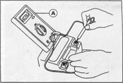
Charging Condition Inspection
Battery charging condition can be checked by measuring battery terminal voltage.
• Remove:
Seat(s)
| > С 1 £ |
• Disconnect the battery terminal leads.
CAUTION
| 1 1 | ||
| I 1 1 • 1 1 | ||
| /1 | ||
| 1 1 1 1 |
| 13.0 12.5 12.0 11.5 |
| 0 25 50 75 100 |
Refreshing Charge
• Disconnect the battery terminal leads (see Charging Condition Inspection).
• Remove the battery [А].
• Refresh-charge by following method according to the battery terminal voltage.
|
|