Главная страница Случайная страница
Разделы сайта
АвтомобилиАстрономияБиологияГеографияДом и садДругие языкиДругоеИнформатикаИсторияКультураЛитератураЛогикаМатематикаМедицинаМеталлургияМеханикаОбразованиеОхрана трудаПедагогикаПолитикаПравоПсихологияРелигияРиторикаСоциологияСпортСтроительствоТехнологияТуризмФизикаФилософияФинансыХимияЧерчениеЭкологияЭкономикаЭлектроника
Suspension
|
|
Table of Contents
Exploded View................................................................................................................................. 12-2
Specifications.................................................................................................................................. 12-4
Front Fork......................................................................................................................................... 12-5
Rebound Damping Force Adjustment.................................................................................. 12-5
Compression Damping Force Adjustment......................................................................... 12-5
Spring Preload Adjustment..................................................................................................... 12-6
Front Fork Removal (each fork leg)...................................................................................... 12-6
Front Fork Installation.............................................................................................................. 12-7
Fork Oil Change......................................................................................................................... 12-7
Front Fork Disassembly........................................................................................................ 12-10
Front Fork Assembly............................................................................................................. 12-11
Inner Tube Inspection........................................................................................................... 12-12
Dust Seal Inspection.............................................................................................................. 12-12
Spring Tension......................................................................................................................... 12-13
Rear Shock Absorber.................................................................................................................. 12-14
Rebound Damping Force Adjustment............................................................................... 12-14
Compression Damping Force Adjustment....................................................................... 12-14
Spring Preload Adjustment.................................................................................................. 12-14
Rear Shock Absorber Removal........................................................................................... 12-15
Rear Shock Absorber Installation....................................................................................... 12-16
Rear Shock Absorber Scrapping........................................................................................ 12-16
Swingarm........................................................................................................................................ 12-17
Swingarm Removal................................................................................................................ 12-17
Swingarm Installation............................................................................................................ 12-18
Swingarm Bearing Removal................................................................................................. 12-18
Swingarm Bearing Installation............................................................................................. 12-18
Tie- Rod, Rocker Arm.................................................................................................................. 12-19
Tie-Rod Removal.................................................................................................................... 12-19
Tie-Rod Installation................................................................................................................ 12-19
Rocker Arm Removal............................................................................................................. 12-19
Rocker Arm Installation......................................................................................................... 12-19
Needle Bearing Inspection................................................................................................... 12-20
Tie-Rod, Rocker Arm Sleeve Inspection.......................................................................... 12-20

|
| Exploded View |
| T1: | 21 N-m (2.1 kg-m, 15.0 ft-lb) | |
| US: U.S.A. | T2: | 28 N-m (2.9 kg-m, 21 ft-lb) |
| CN: Canada | T3: | 23 N-m (2.3 kg-m, 16.5 ft-lb) |
| 1. Fork Spring: Smaller end faces up. | T4: | 15 N-m (1.5 kg-m, 11.0 ft-lb) |
| F: Apply fork oil. | T5: | 39 N-m (4.0 kg-m, 29 ft-lb) |
| L: Apply a non-permanent locking agent. | T6: | 18 N-m (1.8 kg-m, 13.0 ft-lb) |
| M: Apply molybdenum disulfide grease. | T7: | 20 N-m (2.0 kg-m, 14.5 ft-lb) |
| R: Replacement Parts | T8: | 59 N-m (6.0 kg-m, 43 ft-lb) |
| S: Follow the specific tightening sequence. | T9: | 98 N-m (10.0 kg-m, 72 ft-lb) |
| @-< з) |
2. Needle Bearings: Face the manufacturer's marks out.

|
Specifications
| Item | Standard |
| Front Fork (per one unit): | |
| Fork inner tube diameter | Ф 41 mm |
| Fork spring preload setting | Adjuster protrusion is 15 mm (6 Marks) |
| (Usable Range: 5-20 mm) | |
| Air Pressure | Atmospheric pressure (Non-adjustable) |
| Rebound damper setting | 6th click from the first click of the fully clockwise position |
| (Usable Range: 1 «—> 12-13 clicks) | |
| Compression damper setting | 5th click from the first click of the fully clockwise position |
| (Usable Range: 1 «—► 7 ~ 9 clicks) | |
| Fork oil viscosity | KAYABA01 (SAE5W) |
| Fork oil capacity | 463 ± 4 mL (completely dry). |
| ZX900-B3 other than US, CN, 457 ± 4 mL (completely dry) | |
| approx. 395 mL (when changing oil). | |
| 390 mL ZX900-B3 other than US, CN (when changing oil) | |
| Fork oil level | Fully compressed, without fork spring, below from |
| outer tube top 86 ± 2 mm. | |
| ZX900-B3 other than US, CN 90 ± 2 mm | |
| Fork spring free length | 304.6 mm (Service limit 300 mm). |
| ZX900-B3 other than US, CN 387.4 mm | |
| (Service limit 380 mm) | |
| Rear Shock Absorber: | |
| Rebound damper set | No. 2 of 4 positions |
| Compression damper set | 10th click (12th click, ZX900-B3 other than US, CN) |
| from the first click of the fully clockwise position | |
| (Usable Range: 1 «—► 16-22 clicks) | |
| Spring setting position | |
| Standard | Spring free length minus 12 mm |
| Usable range | Spring free length minus 12 mm to 22 mm |
| (weaker to stronger) | |
| ZX900-B3 other than US, CN | |
| Standard | Spring length 212 mm |
| Usable range | Spring length 212 mm to 206 mm (weaker to stronger) |
| Spring Free Length | |
| (ZX900-B3 other than US, CN) | |
| Standard | 226 mm |
| Gas pressure | 980 kPa (10 kg/cm2, 142 psi, Non-adjustable) |
| Special Tools - Fork Spring Compressor 57001-1338 Fork Spring Stopper: 57001-1374 Fork Piston Rod Puller, M10 x 1.0: 57001-1298 Fork Oil Level Gauge: 57001-1290 Fork Outer Tube Weight 57001-1218 Fork Cylinder Holder: 57001-1297 Fork Oil Seal Driver, Ф41: 57001-1288 Steering Stem Nut Wrenches: 57001-1100 (2) Socket Wrench: 57001-1370 Oil Seal & Bearing Remover: 57001-1058 Bearing Driver Set 57001-1129 Inside Circlip Pliers: 57001-143 Jack: 57001-1238 |
Front Fork
Rebound Damping Force Adjustment
|
•To adjust the rebound damping force, turn the rebound damping adjuster [A] until you feel a click.
OThe standard adjuster setting for the average-build rider of 68 kg (150 lb) with no passenger and no accessories is the 6th click from the 1 st click of the fully clockwise position.
A WARNING
N both adjusters are not adjusted equally, handling may be Impaired and a hazardous condition may result.
OThe damping force can be left soft for average riding. But it should be adjusted harder for high speed riding or riding with a passenger. If the damping feels too soft or too stiff, adjust it in accordance with the following table.
Rebound Damping Force Adjustment

| Adjuster Position |
| Damping Force |
| 12 ~ 13 t i 1 |
| Setting |
| Road |
| Speed |
| Load |
| Weak t i Strong |
| Light t i Heavy |
| Good t I Bad |
Compression Damping Force Adjustment

|
•To adjust the compression damping force, turn the compression
damping adjuster [A] until you feel a click. OThe standard adjuster setting for the average-build rider of 68 kg (150 lb) with no passenger and no accessories is the 5th click from the 1 st click of the fully clockwise position.
A WARNING
If both adjusters are not adjusted equally, handling may be Impaired and a hazardous condition may result
OThe damping force can be left soft for average riding. But it should be adjusted harder for high speed riding or riding with a passenger. If the damping feels too soft or too stiff, adjust it in accordance with the following table.
Compression Damping Force Adjustment
|
Spring Preload Adjustment

|
•Turn the spring preload adjuster [A] to change spring preload setting.
OThe standard adjuster setting for the average-build rider of 68 kg (150 lb) with no passenger and no accessories is the 6th mark [A] (15mm) [B] from top as shown.
Adjuster Protrusion (from top)
Standard: 6lh Mark (15 mm) Usable Range 1 ~ Btti Mark (5-20 mm)
AWARNING
И both adjusters are not adjusted equally, handling may be impaired and a hazardous condition may result
| В ■ ma: 4 | ||
| ® --^vv.: - -...л |
OThe spring preload can be left soft for average riding. But it should be adjusted harder for high speed riding or riding with a passenger. If the spring action feels too soft or too stiff, adjust it in accordance with the following table.
Spring Action
|
Front Fork Removal (each fork leg) •Remove:
Upper and Lower Fairings (see Frame chapter) Front Wheel (see Wheels/Tires chapter) Front Fender Rear (see Frame chapter) * Loosen the handlebar holder bolt [A], upper fork clamp bolt [B] and fork top plug [C] beforehand if the fork leg is to be disassembled.
NOTE

|
О Loosen the top plug after loosening the handlebar holder bolt and upper fork damp bolt
• Loosen the handlebar holder bolt [A], upper fork clamp bolt [B] and

|
lower fork clamp bolt [С]. •With a twisting motion, work the fork leg down and out.
Front Fork Installation
• Install the fork so that the top end [A] of the outer tube is flush with the upper surface of the handlebar holder.
•Tighten the lower fork clamp bolt and fork top bolt.
Torque - Front Fork Clamp Bolt (Lower): 28 N-m (2.9 kg-m, 21 ft-lb) Front Fork Top Plug: 23 N-m (2.3 kg-m, 16.5 ft-B>)
•Tighten the handlebar holder bolt and upper fork clamp bolt.
Torque - Handlebar Holder Bolt 23 N-m (2.3 kg-m, 16.5 ft-lb)
Front Fork Clamp Bott (Upper): 21 N-m (2.1 kg-m, 15.0 ft-lb)
NOTE
О Tighten the top plug before tightening the handlebar holder bolt and upper fork damp bolt.

• Install the removed parts (see appropriate chapters). •Adjust the spring preload and the damping force.
Fork Oil Change
• Remove the front fork (see Front Fork Removal).
• Hold the inner tube lower end in a vise.
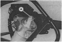
• Unscrew the top plug [A] out of the outer tube [В].
• Insert the fork spring compressor [C] along with the fork spring stopper [D] between the forte top plug and the spacer guide [Е].
Special Tools - Fork Spring Compressor: 57001-1338 Fork Spring Stopper: 57001-1374
*lf the special tools cannot be inserted, turn the spring preload adjuster [F] clockwise until the special tools can be inserted.
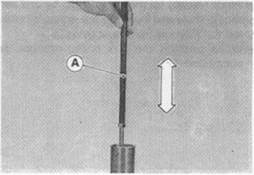
•While holding up the top plug [A] by one person, push down [B] the special tools and insert the fork spring stopper [C] between the piston rod nut [D] and the spacer guide [Е].

|
•While pushing the fork spring stopper, pull out the fork spring compressor [F].
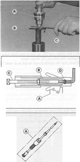
ФHolding the piston rod nut [A] with a wrench [B], remove the fork top plug from the piston rod.
• Remove:
Rebound Damping Adjuster Rod [A] Fork Spring Stopper [B]
NOTE
О While holding down the spacer [C], pull out the fork spring stopper.
• Remove:

Spacer Guide [D] and Spacer Fork Spring
• Drain the fork oil into a suitable container.
О Pump the piston rod [A] up and down at least ten times to expel the oil from the fork.
• Hold the fork tube upright press the outer tube and the piston rod all the way down.
NOTE
О The spring should not be installed.
• Fill the front fork to the top with the specified oil.
Recommended Oil
|
KAY ABA 01 or SAE5W
• Purge the air from the fork cylinder by gently moving the rod puller [A] up and down five times.

|
Special Tool - Fork Piston Rod Puller, M10 x 1.0: 57001-1298
• Purge the air from between the inner and outer tubes by pumping the outer tube up and down.
NOTE
О White doing this. take care to keep the oil level topped off so that it stays above the two holes [A] near the top fo the inner tube [£? ].

|
•After purging the air from the assembly, let it sit for about five minutes so that any suspended air bubbles can surface.
•Set the oil level gauge stopper [A] so that its lower side shows the oil level distance specified.
Special Tool - Fork Oil Level Gauge: 57001-1290 [B]
NOTE
О The gauge tube is graduated in 1 cm division. О The gauge body is graduated in 10 mL division, excluding the gauge tube of about 5 mL capacity.
•With the fork fully compressed, insert the gauge tube into the inner
tube and position the stopper across the top of the outer tube. • Pull the handle slowly to draw out all excess oil.
Oil Level (fully compressed, without fork spring)
Standard: 86 ± 2 mm (below from outer tube top)

|
90 ± 2 mm (below from outer tube top, ZX900-B3 other than US, CN)
• Pull the piston rod [A] up above the outer tube top. •Tighten the rod nut [B] finger-tight О Check that the visible thread length is at least 12 mm [С].
• Insert the rebound damping adjuster rod into the piston rod. •Screw the fork piston rod puller onto the end of the rod.
Special Tool - Fork Piston Rod Puller, M10 x 1.0: 57001-1298
• Install the fork spring with the smaller end facing upward.

|
• Install the spacer and spacer guide.
•While holding up the fork piston rod puller [A] by one person, push down [B] the fork spring compressor [C] and fork spring stopper
[D], and insert the fork spring stopper between the piston rod nut
[E] and the spacer guide [F].
Special Toole - Fork Spring Compressor: 57001-1338 Fork Spring Stopper 57001-1374
•While pushing the fork spring stopper, pull out the fork spring

|
compressor. • Remove the fork piston rod puller.
• Check the O-nng [A] on the top plug and replace it with a new one if damaged.
•Screw in the damper adjuster [B] of the top plug so that the distance between the adjuster bottom and the spring adjuster [C] end is 25 mm [D].
• Holding the top plug [A] with a wrench, tighten the piston rod nut [B] against the top plug.
Torque - Piston Rod Nut 15 N-m (1.5 kg-m, 11.0 fl-lb)
• Remove the fork spring stopper [С].
NOTE
О White holding down the spacer [D], pull out the fork spring stopper.
• Raise the outer tube and screw the top plug into it.
• Install the front fork (see Front Fork Installation).
Front Fork Disassembly
• Remove the front fork (see Front Fork Removal).
• Drain the fork oil (see Fork Oil Change).
• Hold the front fork in a vise [А].
•Stop the cylinder [B] from turning by using the fork cylinder holder [С].

|
Special Toot - Fork Cylinder Holder 57001-1297
• Unscrew the Allen bolt [D], then take the bolt and gasket out of the bottom of the inner tube.
•Take the piston cylinder unit [А]. О Do not disassemble the piston cylinder unit
•Separate the inner tube from the outer tube as follows. OSIide up the dust seal.
О Remove the retaining ring [A] from the outer tube.
О Grasp the inner tube and stroke the outer tube up and down several times. The shock to the fork seal separates the inner tube from the outer tube.
*lf the tubes are tight, use a fork outer tube weight. Special Tool - Fork Outer Tube Weight 57001-1218
(Remove the inner tube guide bushing [A], outer tube guide bushing [B], washer [C], oil seal [D], retaining ring and dust seal from the inner tube.
Front Fork Assembly •Replace the following parts with new one. Oil Seal
Guide Bushings
• Place an oil coated plastic bag [A] over the end of the inner tube to protect the dust seal [B] and oil seal.
OThe inner tube bushing groove has a sharp edge that can cut the sealing lip of the seals as they are pushed down over the inner tube.
• Install the following parts onto the inner tube.
Dust Seal Retaining Ring Oil Seal Washer

Outer Tube Guide Bushing Inner Tube Guide Bushing
•When assembling the new outer tube guide bushing, hold the washer against the new bushing and tap the washer with the fork oil seal driver [A] until it stops.
Special Tool - Fork Oil Seal Driver, Ф41: 57001-1288
•After installing the washer, install the oil seal by using the fork oil seal driver.
• Install the retaining ring and dust seal by hand.
• Install the piston cylinder unit in the inner tube.
• Replace the bottom Allen bolt gasket with a new one.
•Stop the cylinder from turning by using the fork cylinder holder.
Special Tool - Fork Cylinder Holder: 57001-1297 •Apply a non-permanent locking agent to the Allen bolt and tighten it Torque - Front Fork Bottom Allen Bolt 39 N-m (4.0 kg-m, 29 ft-lb)
• Pour in the specified type of oil (see Fork Oil Change).
Inner Tube Inspection
•Visually inspect the inner tube, and repair any damage.
• Nicks or rust damage can sometimes by repaired by using a wet-stone to remove sham edges or raised areas which cause seal damage.
*lf the damage is not repairable, replace the inner tube. Since damage to the inner tube damages the oil seal, replace the oil seal whenever the inner tube is repaired or replaced.
•Temporarily assemble the inner and outer tubes, and pump them back and forth manually to check for smooth operation.
_____________________ CAUTION _______________________
If the Inner tube la badly bent or creased, replace it Excessive bending, followed by subsequent straightening, can weaken the inner tube.
Dust Seal Inspection
• Inspect the dust seals [A] for any signs of deterioration or damage.


|
* Replace it if necessary.
Spring Tension
•Since a spring becomes shorter as it weakens, check its free length
[A] to determine its condition. *lf the spring of either fork leg is shorter than the sen/ice limit, it must be replaced. If the length of a replacement spring and that of the remaining spring vary greatly, the remaining spring should also be replaced in order to keep the fork legs balanced for motorcycle stability.
Spring Free Length
ZX900B1, B2, B3 (US, CN) ZX900-B3
Standard: 304.6 mm 387.4 mm
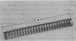
|
Service Limit 300 mm 380 mm
Rear Shock Absorber
Rebound Damping Force Adjustment
•To adjust the rebound damping force, turn the rebound damping adjuster [A] to the desired number [B] until you feel a click and the number aligns with the mark [С].
OThe standard adjuster setting for an average-build rider of 68 kg (160 lb) with no passenger and no accessories is number 2.

| Road |
| Good t i Bad |
| Speed Low t i High |
| Adjuster Position |
| Setting Soft T i Hard |
| Load |
| Light t i Heavy |
*lf the damping feels too soft or too stiff, adjust it Rebound Damping Force Adjustment
Damping Force
Weak t i

|
Strong
Compression Damping Force Adjustment
•To adjust the compression damping force, turn the compression damping adjuster [A] on the gas reservoir until you feel a click.
OThe standard adjuster setting for the average-build rider of 68 kg (150 lb) with no passenger and no accessories is the 10th click (12th click ZX900-B3 other than US, CN) from the 1st click of the fully clockwise position.
OThe damping force can be left soft for average riding. But it should be adjusted harder for high speed riding or riding with a passenger. If the damping feels too soft or too stiff, adjust it in accordance with the following table.
Compression Damping Force Adjustment
|
Spring Preload Adjustment
Refer to P.12-6 for ZX900-B3 other than U.S. and Canadian Models.
• Remove the rear shock absorber from the frame (see Rear Shock Absorber Removal).

|
• Loosen the locknut and turn out the adjusting nut to free the spring.
Special Tool - Steering Stem Nut Wrenches: 57001-1100 (2)
• Measure the spring free length.
•To adjust the spring preload, turn in the adjusting nut [A] to the desired position and tighten the locknut [В]. [C] Spring Length
Spring Preload Setting
Standard: Spring Iree length minus 12 mm Usable Range: Spring free length minus 12 to 22 mm (weaker to stronger)
|
OThe standard adjusting nut setting for an average-build rider of 68 kg (150 lb) with no passenger and no accessories is compressed 12mm than free length. *lf the spring action feels too soft or too stiff, adjust it.
Spring Adjustment
|
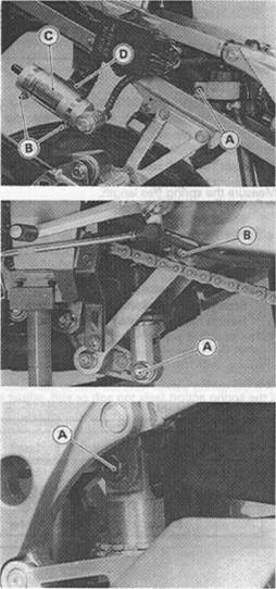
Rear Shock Absorber Removal
• Remove:
Seats (see Frame chapter) Side Covers (see Frame chapter) Fuel Tank (see Fuel System chapter) Battery
Lower Fairings (see Frame chapter) Rear Brake Reservoir Mounting Bolt [A]
• Loosen the clamp screws [B] and remove the gas reservoir [C] from the bracket [D].
• Remove:
Muffler Body (see Engine Top End chapter) Right Lower Fairing Stay Side Stand
• Using the jack, raise the rear wheel off the ground. Special Tool - Jack: 57001-1238

|
• Remove:
Lower Shock Absorber Bolt [A] Upper Tie-Rod Bolt [B]
Upper Shock Absorber Bolt [A] • Remove the shock absorber with the gas reservoir toward the ground.
Rear Shock Absorber Installation
• Pack the rocker arm needle bearings with molybdenum disulfide grease.
•Install the rear shock absorber so that the rebound damping adjuster [A] and gas reservoir hose fitting [B] face rearward.
• Install the gas reservoir clamp screws under the reservoir. •Tighten the following nuts:
Torque - Rear Shock Absorber Nuts: 59 N-m (6.0 kg-m, 43 ft-lb) Tie-Rod Nuts: 59 N-m (6.0 kg-m, 43 ft-lb)
Rear Shock Absorber Scrapping
A WARNING
Since (he reservoir tank of the rear shock absorber contains nitrogen gas, do not incinerate the reservoir tank without first releasing the gas or it may explode.
• Remove the shock absorber (see Rear Shock Absorber Removal).
• Remove the valve cap [A] and release the nitrogen gas completely from the gas reservoir.

|
• Remove the valve.
A WARNING
Since the high pressure gas Is dangerous, do not point the valve toward your lace or body.
Spring Preload Adjustment (ZX900-B3 other than US, CN)
• Remove the rear shock absorber from the frame (see Rear Shock Absorber Removal).
• Loosen the locknut and turn out the adjusting nut to free the spring. Special Tool - Steering Stem Nut Wrench: 57001 -1100 (2)
• Measure the spring free length.
Spring Free Length
Standard:. 226 mm
•To adjust the spring preload, turn in the adjusting nut [A] to the desired position and tighten the locknut [В]. [C] Spring Length
Spring Preload Setting
Standard: Spring length 212 mm
Usable Range: Spring length 212 to 206 mm (weaker to stronger)
OThe standard adjusting nut setting for an average-build rider of 68 kg (150 lb) with no passenger and no accessories is 212 mm spring length.

*lf the spring action feels too soft or stiff, adjust it. Spring Adjustment
| Adjuster | Damping | ||||
| Position | Force | Setting | Load | Road | Speed |
| 212 mm | Weak | Soft | Light | Good | Low |
| t | t | t | t | t | t |
| i | i | i | i | i | |
| 206 mm | Strong | Hard | Heavy | Bad | High |
Swingarm
Swingarm Removal • Remove:

Rear Wheel (see Wheels/Tires chapter) Chain Cover [A] Brake Hose Clamp [B]
Muffler body [C] (see Engine Top End chapter)
Lower Shock Absorber Bolt [A] Upper Tie-Rod bolt [B]
• Unscrew the swingarm pivot locknut [A], using the socket wrench [В].
Special Tool - Socket Wrench: 57001-1370
•Unscrew the swingarm pivot nut [A], and loosen the swingarm pivot shaft [В].
•Pull off the pivot shaft and remove the swingarm.
•Remove th left collar [A] and right collar from the swingarm [В].
Swingarm Installation
•Apply plenty of molybdenum disulfide grease to the ball bearing, needle bearings and grease seals.
• Install the collars, swingarm [A] and pivot shaft [B] as shown. О Place the left collar [Cj on the stopper [D] inside the frame [Е]. О Insert the pivot shaft into the frame from the left side. •Tighten the pivot shaft.
Torque - Swingarm Pivot Shaft 20 N-m (2.0 kg-m, 14.5 ft-lb)
•Tighten the pivot nut.
Torque - Swingarm Pivot Nut 98 N-m (10.0 kg-m, 72 ft-lb)
•Tighten the pivot lock nut [F] using the socket wrench.
Special Tool - Socket Wrench: 57001-1370
Torque - Swingarm Pivot Lock Nut: 98 N-m (10.0 kg-m, 72 ft-lb)

|

|

|
| Swingarm Bearing Installation •Apply plenty of molybdenum disulfide to the ball bearing and needle bearings. • Install the bearings so that the manufacturer's marks face out. Special Tool - Bearing Driver Set 57001-1129 [A] |
• Install the removed parts (see appropriate chapters).
Swingarm Bearing Removal
• Remove:
Swingarm Collars Grease Seals Sleeve
Circlip (right side) Special Tool - Inside Circlip Pliers: 57001-143
• Remove the ball bearing and needle bearings using the oil seal & bearing remover [А].

|
Special Tool - Oil Seal & Bearing Remover: 57001-1058
Tie-Rod, Rocker Arm
Tie-Rod Removal
• Remove:
Upper and Lower Fairings (see Frame chapter) Radiator (see Cooling System chapter) Muffler (see Engine Top End chapter)
• Using the jack, raise the rear wheel off the ground.
Special Tool - Jack: 57001-1238
• Remove the upper tie-rod bolt [A] and lower tie-rod bolt [B], and take out the tie-rods [С].
Tie-Rod Installation
•Apply molybdenum disulfide grease to the inside of the needle
bearings and oil seals. •Tighten the upper and lower tie-rod bolts.

|
Torque - Tie-Rod Nuts: 59 N-m (8.0 kg-m, 43 ft-lb)
Rocker Arm Removal
• Remove:
Upper and Lower Fairings (see Frame chapter) Radiator (see Cooling System chapter) Muffler (see Engine Top End chapter)
• Using the jack, raise the rear wheel off the ground.
Special Tool - Jack: 57001-1238
• Remove:
Lower Rear Shock Absorber Bolt [A] Lower Tie-Rod Bolt [B] Rocker Arm Bolt [C] Rocker Arm [D]
Rocker Arm Installation
•Apply molybdenum disulfide grease to the inside of the needle
bearings and oil seals. •Tighten the rocker arm bolt, tie-rod bolt and shock absorber bolt.

|
Torque - Rocker Arm Nut 59 N-m (8.0 kg-m, 43 ft-lb) Tie-Rod Nut 59 N-m (6.0 kg-m, 43 ft-lb) Rear shock Absorber Nut: 59 N-m (6.0 kg-m, 43 ft-lb)
Needle Bearing Inspection
*lf there is any doubt as to the condition of eigher needle bearing, replace the bearing and sleeve as a set.
lie-Rod, Rocker Arm Sleeve Inspection
*lf there is visible damage, replace the sleeve and needle bearing as a set.
|
|