Главная страница Случайная страница
Разделы сайта
АвтомобилиАстрономияБиологияГеографияДом и садДругие языкиДругоеИнформатикаИсторияКультураЛитератураЛогикаМатематикаМедицинаМеталлургияМеханикаОбразованиеОхрана трудаПедагогикаПолитикаПравоПсихологияРелигияРиторикаСоциологияСпортСтроительствоТехнологияТуризмФизикаФилософияФинансыХимияЧерчениеЭкологияЭкономикаЭлектроника
Engine Top End
|
|
Table of Contents
Exploded View................................................................. 4-2
Specifications.................................................................. 4-4
Clean Air System............................................................. 4-6
Air Suction Valve Inspection...................................... 4-6
Vacuum Switch Valve Installation.............................. 4-6
Vacuum Switch Valve Test......................................... 4-6
Clean Air System Hose Inspection............................ 4-7
Cylinder Head Cover....................................................... 4-8
Cylinder Head Cover Removal.................................. 4-8
Cylinder Head Cover Installation............................... 4-8
Camshaft Chain Tensioner.............................................. 4-9
Camshaft Chain Tensioner Removal......................... 4-9
Camshaft Chain Tensioner Installation...................... 4-9
Camshaft, Camshaft Chain............................................ 4 10
Camshaft Removal................................................... 4-10
Camshaft Installation................................................ 4-10
Camshaft, Camshaft Cap Wear................................ 4-11
Camshaft Chain Removal......................................... 4-12
Camshaft Chain Wear............................................... 4-12
Rocker Shaft Rocker Arm.............................................. 4-13
Rocker Shaft, Rocker Arm Removal........................ 4-13
Rocker Shaft. Rocker Arm Installation..................... 4-13
Cylinder Head................................................................ 4-14
Cylinder Compression Measurement...................... 4-14
Cylinder Head Removal........................................... 4-14
Cylinder Head Installation........................................ 4-15
Valves............................................................................ 4-16
Valve Clearance Adjustment..................................... 4-16
Valve Removal.......................................................... 4-20
Valve Installation....................................................... 4-20
Valve Guide Removal............................................... 4-20
Valve Guide Installation............................................ 4-20
Valve-to-Guide Clearance Measurement
(Wobble Method)..................................................... 4-20
Valve Seat Inspection................................................ 4-21
Valve Seat Repair...................................................... 4-21
Seat Cutter Operation Care:................................ 4-22
Marks Stamped on the Cutter:............................. 4-22
Operating Procedures:......................................... 4-22
Cylinder, Pistons............................................................ 4-25
Cylinder Removal...................................................... 4-25
Cylinder Installation.................................................. 4-25
Piston Removal......................................................... 4-25
Piston Installation...................................................... 4-26
Cylinder Wear............................................................ 4-26
Piston Wear............................................................... 4-27
Piston Ring, Piston Ring Groove Wear.................... 4-27
Piston Ring End Gap................................................. 4-27
Carburetor Holder........................................................... 4-28
Carburetor Holder Installation................................... 4-28
Muffler............................................................................. 4-29
Muffler Removal........................................................ 4-29
Muffler Installation..................................................... 4-29
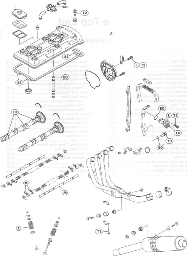
Exploded View
1. Arrow points to the front.
2. Closed coil end faces downward.
3. R marked side faces up. С A: California
L: Apply a non-permanent locking agent. M: Apply molybdenum disulfide grease. EO: Apply engine oil. R: Replacement Parts
Follow the specific tightening sequence. SS: Apply silicone sealant
| (s> -f |
| s)—% |
(Kawasaki Bond: 56019-120).

|
T3: T4: T5: T6: T7: T8: T9:

|
Specifications
| Item | Standard | Service Limit |
| Clean Air System: | ||
| Vacuum switch valve closing pressure: | Open -» Close | |
| 57 - 65 к Pa (430 - 490 mmHg) | ---------- | |
| Camshafts | ||
| Cam height: Exhaust | 36.480 - 36.620 mm. | 36.38 mm |
| 35.063 - 35.179 mm (FR) | 34.96 mm | |
| Inlet | 36.667 - 36.807 mm, | 36.56 mm |
| 35.063 - 35.179 mm (FR) | 34.96 mm | |
| Camshaft journal, camshaft cap clearance | 0.048 - 0.091 mm (#1, #4) | 0.18 mm |
| 0.078 - 0.121 mm (#2, #3) | 0.21 mm | |
| Camshaft journal diameter | 23.930 - 23.952 mm (#1, #4) | 23.90 mm |
| 23.900 - 23.922 mm (#2, #3) | 23.87 mm | |
| Camshaft bearing inside diameter | 24.000 ~ 24.021 mm | 24.08 mm |
| Camshaft runout | TIR 0.02 mm or less | TIR 0.1 mm |
| Camshaft chain 20-link length | 127.00 - 127.36 mm | 128.9 mm |
| Rocker arm inside diameter | 12.000 ~ 12.018 mm | 12.05 mm |
| Rocker shaft diameter | 11.966 - 11.984 mm | 11.94 mm |
| Cylinder Head: | ||
| Cylinder compression | (usable range) 960 - 1 470 kPa (9.8 - 15.0 kg/cm2, 139 - 213 psi) @340 r/min (rpm) | ---------- |
| Cylinder head warp | ---------- | 0.05 mm |
| Valves: | ||
| Valve clearance: Exhaust | 0.21 - 0.26 mm | ---------- |
| Inlet | 0.18 - 0.23 mm | ---------- |
| Valve head thickness: Exhaust | 0.7 - 0.9 mm | 0.5 mm |
| Inlet | 0.4 - 0.6 mm | 0.25 mm |
| Valve stem bend | TIR 0.01mm or less | TIR 0.05 mm |
| Valve stem diameter: Exhaust | 4.455 - 4.470 mm | 4.44 mm |
| Inlet | 4.475 - 4.490 mm | 4.46 mm |
| Valve guide inside diameter Exhaust | 4.500 - 4.512 mm | 4.58 mm |
| Inlet | 4.500 - 4.512 mm | 4.58 mm |
| Valve/valve guide clearance | ||
| (wobble method): Exhaust | 0.090 - 0.171 mm | 0.37 mm |
| Inlet | 0.031 - 0.113 mm | 0.32 mm |
| Valve seat cutting angle | 45*, 32*, 60° | ---------- |

|
| Item | Standard | Service Limit | |
| Valve seat surface: | |||
| Width: | Exhaust | 0.5 - 1.0 mm | — — |
| Inlet | 0.5 - 1.0 mm | ---------- | |
| Outside diameter: | Exhaust | 24.4 ~ 24.6 mm | ---------- |
| Inlet | 28.4 ~ 28.6 mm | ---------- | |
| Valve spring free length: | Exhaust Inlet | 41.8 mm | 40.1 mm |
| Cylinder, Piston: | |||
| Cylinder inside diameter | 73.000 - 73.012 mm | 73.1 mm | |
| Piston diameter | 72.942 - 72.958 mm | 72.8 mm | |
| Piston/cylinder clearance | 0.042 ~ 0.070 mm | ---------- | |
| Piston ring/groove clearance: Top | 0.05 - 0.09 mm | 0.19 mm | |
| Second | 0.03 - 0.07 mm | 0.17 mm | |
| Piston ring groove width: | Top | 0.84 - 0.86 mm | 0.94 mm |
| Second | 0.82 ~ 0.84 mm | 0.92 mm | |
| Piston ring thickness: | Top | 0.77 ~ 0.79 mm | 0.70 mm |
| Second | 0.77 - 0.79 mm | 0.70 mm | |
| Piston ring end gap: | Top | 0.20 - 0.35 mm | 0.65 mm |
| Second | 0.20 - 0.35 mm | 0.65 mm | |
| Oil | 0.20 ~ 0.70 mm | 1.0 mm |
(FR): France

|
Special Tools - Fork Oil Level Gauge: 57001-1290 Vacuum Gauge: 57001-1369 Spark Plug Wrench, 16mm: 92110-1154 Compression Gauge: 57001-221 Compression Gauge Adapler, M10 X 1.0: 57001-1317 Hexagon Wrench, Hex 8: 57001-1234 Valve Spring Compressor Assembly: 57001-241 Valve Spring Compressor Adapter, Ф22: 57001-1202 Valve Guide Arbor, Ф4.5: 57001-1331 Valve Guide Reamer, Ф4.5: 57001-1333 Valve Seat Cutter, 45" - Ф32: 57001-1115 Valve Seat Cutter, 32° - Ф30: 57001-1120 Valve Seat Cutter, 60° - Ф30: 57001-1123 Valve Seat Cutter, 45° - Ф27.5: 57001-1114 Valve Seat Cutter, 32° - Ф28: 57001-1119 Valve Seal Cutter Holder, Ф4.5: 57001-1330 Valve Seat Cutter Holder Bar: 57001-1128 Piston Ring Compressor Grip: 57001-1095 Piston Ring Compressor Belt, Ф67 - Ф79: 57001-1097 Piston Pin Puller Assembly: 57001-910 Piston Ring Pliers: 57001-115

|
Sealant - Kawasaki Bond (Silicone Sealant): 56019-120
| /TV" •:: |

|

Clean Air System
Air Suction Valve Inspection
•Visually inspect the reeds [A] for cracks, folds, warps, heat damage, or other damage.
*lf there is any doubt as to the condition of the reed, replace the air suction valve as an assembly.
•Check the reed contact areas [B] of the valve holder for grooves, scratches, any signs of separation from the holder, or heat damage.
*lf there is any doubt as to the condition of the reed contact areas, replace the air suction valve as an assembly.
*lf any carbon or other foreign particles have accumulated between the reed and the reed contact area, wash the valve assembly with a high flash-point solvent
•Gradually raise the vacuum (lower the pressure) applied to the vacuum switch valve, and check the valve operation. When the vacuum is low, the vacuum switch valve should permit air to flow. When the vacuum raises to 57 - 65 kPa (430 ~ 490 mm Hg), it should stop air flow. *lf the vacuum switch valve does not operate as described, replace it with a new one.
NOTE

| 1. During Cruising (open throttle) Spring ^ Diaphragm Valve |

О To check air flow through the vacuum switch valve, just blow through the air cleaner hose.
| Secondary air flows. 2. During Engine Braking |

| High Secondary air cannot flow. |
Vacuum Switch Valve Closing Pressure (Open Close) Standard: 57 -65 kPa (430 - 490 mmHg)
Clean Air System Hose Inspection • Be certain that all the hoses are routed without being flattened or kinked, and are connected correctly to the air cleaner housing, vacuum switch valve, #1 and #4 carburetors and air suction valve covers. *lf they are not correct them. Replace them if they are damaged.
Cylinder Head Cover
Cylinder Head Cover Removal
• Remove:
Seats (see Frame chapter)
Air Cleaner Housing (see Fuel System chapter)
Vacuum Switch Valve and Hoses
Ignition Coils

|
Bolt [A] and Baffle Plate [B]
• Remove the cylinder head cover bolts [C] and take off the cover [DJ.
Cylinder Head Cover Installation

|
•Apply silicone sealant to the cylinder head as shown [А].
• Replace the head cover gasket with a new one if damaged. •Apply silicone sealant to the right and the wrong side at the areas [A] of the head cover gasket [B] as shown.
• Check that the upper chain guide [A] bottoms out in the head cover.
CAUTION
Camshaft Chain Tensioner
Camshaft Chain Tensioner Removal
|
|