Главная страница Случайная страница
Разделы сайта
АвтомобилиАстрономияБиологияГеографияДом и садДругие языкиДругоеИнформатикаИсторияКультураЛитератураЛогикаМатематикаМедицинаМеталлургияМеханикаОбразованиеОхрана трудаПедагогикаПолитикаПравоПсихологияРелигияРиторикаСоциологияСпортСтроительствоТехнологияТуризмФизикаФилософияФинансыХимияЧерчениеЭкологияЭкономикаЭлектроника
Equipment forming control signals and management
|
|
Beacon VOR-4000 generates and emits a complex set of azimuth signals, reference and recognition (rys.5.11). In addition, the beacon provides for the possibility of transmission on board the aircraft of the speech signal.
In technical documentation beacon VOR-4000, azimuth and reference signals labeled respectively " side frequency signals" and " signals the carrier frequency", the pointed absence of radiation azimuth signal carrier frequency and availability of the full range of frequency in the reference signal.
Azimuthal signal (frequency side) obtained after balancing modulation (BM) carrier frequency of the two signals at 30 Hz, which differ in phase by 90 °. Two BM signals emitted crossed vibrators. Reference signal (carrier) is the RF carrier frequency vibrations that tension AM subcarrier frequency of 9960 Hz. Subcarrier frequency signal in turn FM voltage at 30 Hz, which is the same phase with the phase voltages 30Hz bass one of the components azimuth signal. The spectrum of emitted signals shown in rys.5.12. The reference signal emitted omnidirectional antenna

Figure 2.6 Formation azimuth signal beacon VOR-4000:
А - directional antenna diagram;
В - side form azimuthal frequency signals
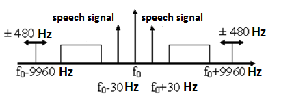
Figure 2.7 The range of radio signals VOR-4000
The equipment consists of forming signal exciter, three amplifiers, modulators (Exiter-AF), modulating oscillation generator and power amplifiers (rys.5.13).
Exciter generates highly stable signal carrier frequency in the range 108... 112 MHz. In addition, some signal exciter used in equipment control and radio controls as a standard (reference) signal. Exciter frequency adjusted to the working channel replacement removable crystal. In exciters crystal oscillator signals and amplified by dividers and buffer amplifiers distributed on inputs amplifiers, modulators MOD 110 carrier frequencies CSG and side SB1 and SB2. To ensure sustainability output amplitude in amplifiers used exciter circuit automatic signal amplification crystal oscillator. From the initial stages of the exciter signal is removed for control. Output signals are modulated in amplitude exciter three amplifiers MOD-110.
MOD-in amplifiers 110 formed azimuth and bearing radio signals. In forming the channel reference signal MOD-110 provides carrier frequency AM radio signal detection and if necessary - speech signal. All three amplifiers collected by the same scheme.
High-frequency signals are fed to the input of the amplifier ultra high frequency (UHF) through fazokorektuyuchi preliminary stages and amplifier. By microwave amplifier signal generator modulating oscillation coming in after amplification cascade bass enhancement. MOD-in amplifier circuit 110 provides correction phase RF signal cascades of amplification and linearization control voltage coming from the block SSR, and automatic gain control and LF bands perepuskannya amplifier signals monitoring equipment and control. From BM switched phase inverter control circuit. Selecting the operation and management of MOD-110 by using a set of switches (S1-S10). The output of the microwave amplifier AM signal fed to the respective amplifier. Part of the output amplifier MOD-110 is removed to control. MOD-110 amplifiers provide signal amplification up to 20 mW if the input level of 10 MW.
Sometimes it is necessary to determine at what radials is currently plane. To do this, turn the dial to the OBS until the instrument direction arrow points to the TO, and the deviation of the bar will not be strictly vertical. Putting on the map received number VOR-radials, you can estimate your location. However, this method does not show the distance to the VOR.
But VOR-station may have another and distance measuring equipment (DME - Distance Measurement Equipment). Radio stations with such equipment are indicated on the map VOR-DME or VORTAC. You will see the distance in NM to VOR-station on the dashboard or in the window DME1 DME2 respectively. Now, knowing the scale of the map, it may be noted on the VOR-radials exact location of the aircraft at a given time.
Often the distance DME, which you see on the dashboard does not correspond to the distance on the map. This is the distance from the ground VOR-station to your aircraft flying at a certain height. Those. is the hypotenuse of a right triangle, whose one leg - your height, and the second - the distance by land from the VOR-station, to the point on which you are flying right now. Especially these data are inaccurate when you are close to the VOR-station (flying directly over it you get your height). Therefore, it is necessary to reserve one or two miles, if the corridor to controlled airspace requires the mandatory to communicate with the dispatcher when flying the VOR-station. Frequent navigation task - to intercept a specified radial. For example, we need to enter the airway, which takes place on 30 th radial for the VOR. We know that we are somewhere in the left radial (and if you do not know, we can define it as described above):
The first thing we need to do - is to tune into the frequency of VOR and enter using the setpoint OBS desired radial. The device will display something like this:

From this it is evident that the radial somewhere far to the right. Now you have to decide what angle we intercept radial. The fastest way to intercept radial - fly perpendicular to it, but it does not bring us closer to the end point of the route. Choose a reasonable compromise and move at an angle of 40 degrees to the radial for. Since the radial is to the right, to get the interception course, add to the rate of radial (30 °) intercept angle (40 degrees), and obtain the interception rate (70 degrees). If radial is to the left corner of the interception would have to take.

Figure 2.8 Block diagram of signals forming apparatus
beacon VOR-4000
Construction equipment control and radio controls based on the use of microprocessor technology with additional blocks of memory. In beacon VOR-4000 uses two types of control: held and external. Held control parameters are transformation outputs of basic units and units in numerical beacon code and comparing their values in the blocks of memory zberezhuvanymy nominal values of the parameters monitored signals. Tract external control consists of controlling the vibrator unit and monitor. The results are processed by central control processor hardware.
In the beacon is the ability to set (adjust) and to display a number of parameters important radio:
• Power PRD (signal carrier frequency and side);
• depth of modulation and phase RF signals PRD;
• voltage and current supply.
Setting required parameters, and challenge their values and reflection carried out with keyboard and
display unit. Thus are displayed nominal and current values of these parameters.
The CPU consists of hardware processor CPU and memory block MEM. How CPU with hardware forming radio signals carried on three tires communications, control and inspection PRD, monitoring and changing conditions.
The main functions of the CPU CPU:
• Determining the nominal values and the introduction of radio signals forming apparatu
• Signal Processing and held outside control;
• Diagnostic procedures for determining the depth of failures at removable circuit boards;
• Forming teams switching from the main radio sets on or off reserve system;
• communicating with keyboard and display unit.
The combination of CPU processor block keyboard and display through a standard interface.
The main navigation tool in most countries is the VOR (VHF Omnidirectional Range navigation system), which translated into Russian calls omnidirectional localizer VHF. Appeared in recent satellite navigation systems do not replace the VOR, but complement them.
Planes fly in the airways, which are constructed from segments. The segments form a network that entangles the whole country. The nodes of the network (at the endpoints) located VOR-station.
VOR Beacon includes two transmitters at frequencies 108, 00-117, 95 MHz. First VOR transmitter sends a constant signal in all directions, while the second transmitter VOR is a unidirectional rotating beam, changing the phase depending on the angle of rotation, that is, the beam runs through the circle into 360 degrees (as the beam of a lighthouse). The result is a radiation pattern in the form of beams 360 (one beam through each degree of the circle). The receiving apparatus compares the two signals and determines the " beam angle", which is currently in the aircraft. This angle is called VOR-a radial (VOR Radial).
VOR-equipment on board the aircraft can determine which of the VOR radials-known radio
station is a plane.
|
|