Главная страница Случайная страница
Разделы сайта
АвтомобилиАстрономияБиологияГеографияДом и садДругие языкиДругоеИнформатикаИсторияКультураЛитератураЛогикаМатематикаМедицинаМеталлургияМеханикаОбразованиеОхрана трудаПедагогикаПолитикаПравоПсихологияРелигияРиторикаСоциологияСпортСтроительствоТехнологияТуризмФизикаФилософияФинансыХимияЧерчениеЭкологияЭкономикаЭлектроника
Radio receivers
|
|
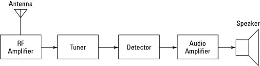
A radio receiver is the opposite of a radio transmitter. It uses an antenna to capture radio waves, processes those waves to extract only those waves that are vibrating at the desired frequency, extracts the audio signals that were added to those waves, amplifies the audio signals, and finally plays them on a speaker.
- Antenna: captures the radio waves. Typically, the antenna is simply a length
of wire. When this wire is exposed to radio waves, the waves induce a very small alternating current in the antenna.
- RF amplifier: A sensitive amplifier that amplifies the very weak radio
frequency (RF) signal from the antenna so that the signal can be processed by the tuner.
- Tuner: A circuit that can extract signals of a particular frequency from a mix
of signals of different frequencies. On its own, the antenna captures radio waves of all frequencies and sends them to the RF amplifier, which dutifully amplifies them all.
Unless you want to listen to every radio channel at the same time, you need a
circuit that can pick out just the signals for the channel you want to hear. That’s the role of the tuner.
The tuner usually employs the combination of an inductor (for example, a
coil) and a capacitor to form a circuit that resonates at a particular frequency. This frequency, called the resonant frequency, is determined by the values chosen for the coil and the capacitor. This type of circuit tends to block any AC signals at a frequency above or below the resonant frequency.
You can adjust the resonant frequency by varying the amount of inductance
in the coil or the capacitance of the capacitor. In simple radio receiver circuits, the tuning is adjusted by varying the number of turns of wire in the coil. More sophisticated tuners use a variable capacitor (also called a tuning capacitor) to vary the frequency.
- Detector: Responsible for separating the audio information from the carrier
wave. For AM signals, this can be done with a diode that just rectifies the alternating current signal. What is left after the diode has its way with the alternating current signal is a direct current signal that can be fed to an audio amplifier circuit. For FM signals, the detector circuit is a little more complicated.
- Audio amplifier: This component's job is to amplify the weak signal that
comes from the detector so that it can be heard. This can be done using a simple transistor amplifier circuit.
Of course, there are many variations on this basic radio receiver design. Many receivers include additional filtering and tuning circuits to better lock on to the intended frequency — or to produce better-quality audio output — and exclude other signals. Still, these basic elements are found in most receiver circuits.
5. Read the text and tell about the design and principle of operation of a
super heterodyne receiver. Use the bloc diagram:
|
|