Главная страница Случайная страница
Разделы сайта
АвтомобилиАстрономияБиологияГеографияДом и садДругие языкиДругоеИнформатикаИсторияКультураЛитератураЛогикаМатематикаМедицинаМеталлургияМеханикаОбразованиеОхрана трудаПедагогикаПолитикаПравоПсихологияРелигияРиторикаСоциологияСпортСтроительствоТехнологияТуризмФизикаФилософияФинансыХимияЧерчениеЭкологияЭкономикаЭлектроника
Storebaelt Reverts to Ballasted Track
|
|
From Railway Gazette International, February 1997
Choose the best heading for each part of the text.
Tunnel track
Choice of track design
Drainage
Expansion joins
A. ……………………………………..
Although slab track was originally to have been laid in the Storebaelt tunnel in Denmark, failure to optimize the choice of track with the diameter of the tunnel at the design stage led to a compromise using ballasted track.
The task force investigated different slab track structures from Japan, England, Italy, France and Germany, assessing them from a technical economic point of view and comparing them with ordinary ballasted track.
The choice fell on ballasted track for the West Bridge, with an Italian design of slab track in the tunnel. On the bridge the track structure is a standard DSB design using UIC60 rails and monoblock concrete sleepers on 350 mm of crushed stone ballast. This rests directly on the bridge deck with no ballast mat.
B. ……………………………………….
To accommodate the longitudinal and rotational movements of the bridge associated with different temperatures, special expansion joints were needed. These require specialist maintenance, so DSB sought to minimize their use to keep costs down.
The bridge superstructure is therefore sectioned with five expansion joints on the deck slab, with a further joint at each abutment. The five bridge joints are located where the bridge girders rest on piers. Each of the five joints on the bridge compensates for an expansion of 1 100 m length of bridge slab, and the joints at the abutments are designed to cope with expansion of 550 m.
The five expansion joints on the bridge are based on a Japanese design. This consists of three small beams forming transition slabs, which are held together by two pin-joints. In principle, the three slabs are held in the same absolute position by an equalizer, and the bridge girders are free to move backwards or forwards with temperature changes without the transition slabs moving across the expansion joint.
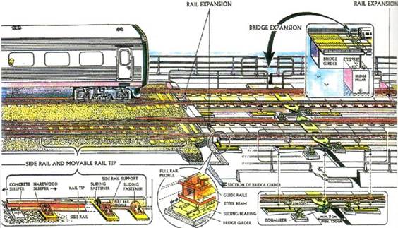
The three transition slabs are fastened to the bridge girders on sliding bearings. Sliding expansion rails are placed in the track, back-to-back on both sides of the joint.
The design ensures that longitudinal and rotational movements are kept separate and can take place in the track structure. The rotation of the bridge is transferred to the track structure by the two pin-joints holding the transition slabs supporting the track. The rotation of the bridge is divided so that half the movement occurs at each pin-joint.
The longitudinal movement of the bridge is distributed in a similar manner between to points on the track. Expansion of the track structure occurs at the ends of the transition slabs, shown as ‘rail expansion’ in the drawing. Expansion of the bridge girders keep changing the gap between the ballast retaining wall on the girder and the end of the transition slabs.
The two pairs of expansion rails at the abutments are fashioned as single expansion rails on the ballast. At the joints on the piers the double expansion rails are placed in the ballasted track on each side of the pin-jointed beams. Sleepers for the expansion are made of the hardwood.
The track over the pin-jointed beams rests directly on the steel beams and uses the full rail profile. Double elastic fastenings are fitted. At this point the guide rails comprise an angle section placed on the outside of each side of the track.
C………………………………………………..
The choice of an Italian slab track design for the East Tunnel was technically the best. It was related to a Japanese design, and tests had shown that it offered excellent performance. But boring had already begun to an internal diameter of 7.7 m, and this could not be altered.
Further investigations revealed that traditional ballasted track could be used. Cleaning the ballast was the most critical maintenance operation, but it could be carried out with a modified ballast cleaning machine. Some dust was thrown up from the ballast during the initial running trials at 180 km/h, but this was easily cured by washing all of the ballast with plain water over a period of about a week.
Cleaning the ballast was the most critical maintenance operation, but it could be carried out with a modified ballast cleaning machine. Some dust was thrown up from the ballast during the initial running trials at 180 km/h, but this was easily cured by washing all of the ballast with plane water over a period of about a week.
D…………………………………………………
A drain runs to a sump at the deepest point, from where water is pumped out. It was originally intended to construct two sumps outside the tunnel using 12 m deep wells. In practice, the very difficult boring conditions meant that the location of sumps was moved to the deepest point of the tunnel. The track was raised as much as possible over a length of 100 m and placed on a concrete slab over the sump.
The track rests on the slab using a double elastic construction similar to the structure resting on the steel beams of the West Bridge. Each section of the track is fastened to the concrete slab by four bolts fixed to 130 mm glued synthetic tenons. The directly mounted track structures are embedded in 25 mm of epoxy resin.
|
|