Главная страница Случайная страница
Разделы сайта
АвтомобилиАстрономияБиологияГеографияДом и садДругие языкиДругоеИнформатикаИсторияКультураЛитератураЛогикаМатематикаМедицинаМеталлургияМеханикаОбразованиеОхрана трудаПедагогикаПолитикаПравоПсихологияРелигияРиторикаСоциологияСпортСтроительствоТехнологияТуризмФизикаФилософияФинансыХимияЧерчениеЭкологияЭкономикаЭлектроника
Function and structure of the navigation channel signals VOR
|
|
Goniometric VOR navigation channel is designed to determine the azimuth of the aircraft with respect to the radio navigation points, which sets ground equipment systems. It includes ground and airborne equipment in the structure of the angular channel. Ground-based equipment is a beacon that radiates signals, reception and processing of which on board the aircraft to determine its azimuth. On-board equipment is a receiver-principle of operation is determined by the method used in the channel azimuth measurement. In this arrangement, the azimuth it is not limited channel bandwidth. Currently, there are three main versions of goniometric systems MW range:
the measurement phase of the envelope fluctuations AM (VOR);
with two-phase measurement (PVOR);
using the Doppler effect (DVOR).
VOR. VOR beacons are two transmit antennas:
A1 omnidirectional antenna with directivity pattern (beam) in a horizontal plane  (2.1);
A2 directional antenna radiation pattern in the horizontal plane  (2.2).
In any azimuthal direction  A2 value orientation diagram is characterized by the
  (2.3).
The antenna A1 creates a field strength  (2.4)
(2.4)
with amplitude  .
.
The antenna A2 in any azimuthal direction It creates a field
 (2.5)
(2.5)
with amplitude  . (2.6)
Usually beacons VOR condition  .
.
High-frequency signals are generated and emitted by a transmitter antenna having a common phase center. When adding fields in the space formed by the total field omnidirectional RM (Fig. 1.6 (b)  (2.7).

Fig. 2.9. VOR beacon radiation pattern of antennas
Taking into account the expressions (1.2 and (1.3 the value of the total field can be expressed as  . (2.8).)
Diagram of A2 rotates in the horizontal plane with an angular velocity  (2.9),
where n - DNA per minute speed.
Duration of one revolution T is the period of rotation,  (2.10), frequency
  (2.11),
VOR rotational frequency is n = 1800 rev / min (F = 30 Hz).
The position of the radiation pattern A2 (position of its maximum- a function of time
The rotation of the antenna is a periodic change in the total field. Let the amplitude ratio  (2.12)and substituting in (1.4 values
  , , we get
 . (2.13)
The result is a field with the depth of amplitude modulation, frequency modulation  envelope and phase dependent on the azimuth . Fluctuations taken onboard receiver may be expressed as
  , (2.14)
where K - coefficient taking into account the weakening.
After amplification and detection can isolate low frequency voltage
 , (2.15)
phase of which contains information about the azimuth of the aircraft :
 . (2.16)
To highlight this information on board the aircraft, you must have a reference oscillation carrying information about the instantaneous position of the bottom. This information should be incorporated in the phase of the reference oscillation  (2.17)
with the current value of the phase  (2.18)
the corresponding angular position of the beam at the time t.
In the presence on board of such aircraft reference voltage can be determined as the aircraft azimuth reference phase difference and azimuth signals:  (2.19).
To use the on-board meter needs a reference signal, and the same for all aircraft. This signal must be transmitted on a separate channel. In order to reduce the frequency reference signal communication channels in such systems transmitting at the same carrier frequency  as the azimuth. Separation of the azimuth and reference signals takes place through the channels on the reception side frequency selection method of the detected amplitude
Consider the formation of the signal ground equipment and aircraft equipment on the example of a simplified block diagram of the channel VOR (Fig. 1.7).
The transmitter (AML formed high-frequency vibrations . The power divider (DM) RF signal is split into two channels. Part of the power supplied to the rotating antenna A2. antenna rotation speed is determined by the control unit (ACU) and is equal to F = 30 Hz. The beacons used various methods of rotation of the antenna. The first antenna rotating beacons carried out mechanically by means of an electric motor. Another method involves the use of goniometric antenna systems. Later electron beam rotation methods have been developed (electronic goniometer method) in which the beam rotation effect is powered from two mutually perpendicular directional antennas with diagrams in the form of eight. Power antenna made of balance-modulated oscillations of phase modulation envelope through 90 °. Antenna A2 creates an electromagnetic field (1.2).
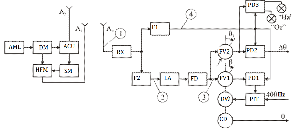
Figure 2.10 Block diagram of a channel VOR
A1 is an omnidirectional antenna and is designed to form a total radiation
pattern " cardioid" type transmission and the reference signal. For a signal with double frequency modulation amplitude is chosen oscillation frequency is much greater speed beam but substantially less than the frequency carrier waves, and use these as auxiliary oscillation. Auxiliary fluctuations are called sub-carrier for which must fulfill the conditions  , and
, and  – subcarrier frequency oscillations. For VOR system subcarrier frequency is HO = 9960 Hz.
The subcarrier modulator (SM is performed subcarrier frequency modulation of the reference oscillation frequency FOP = 30 Hz frequency deviation Δ FP = 480 Hz when the index of modulation  .
.
The HFM modulator high-frequency vibrations in amplitude modulated voltage subcarrier modulation depth  .
.
The antenna A1 creates a field strength
 , (2.20)
where  – Amplitude modulation factor;
  The frequency modulation factor;
  – deviation of the subcarrier frequency.
The total field (2.21)
affects avionics antenna A0. The output of the antenna receives a total swing type  . (2.22)
The amplitude-frequency spectrum of the fluctuations in the total shown in figure

Fig. 2.11. The amplitude-frequency spectrum:
a) a received signal; b) the envelope of the received signal
Airborne equipment must be isolated from the total azimuth and the reference signals and to produce a comparison phase.
After converting the sum signal in the receiver (RX) amplification and detection of its allocated envelope amplitude detector comprising an azimuthal bearing type signals like  , (2.23)
where  и
и  – full amplitude signal components.
From the spectrum of the signal (1.12) shown in Fig. 1.8 (b), it is seen that the azimuth and the reference signals can be distinguished by frequency selection. For this purpose, the output signal Rx is supplied to two filters F1 and F2.
The filter F1 tuned to the frequency  (F = 30 Hz), allocated azimuth signal or a variable phase, and the filter F2 tuned to the subcarrier frequency (F = 9960 Hz, is allocated a frequency-modulated subcarrier oscillation. After symmetric restrictions limiting amplifier (LA) in the frequency detector (FD) is allocated the reference oscillation.
As a result, changes were obtained:
azimuth signal  (2.23);
reference signal (2.24).
The reference voltage is supplied to the phase shifters FV1 and FV2. In the initial position FV1 axis rotated to any angle b, which causes an additional shift of the voltage reference phase by an amount b
 и
и  . (2.25)
Azimuth and the reference voltage is applied to the phase detector PD1. Phase difference between the input voltage  (2.26)
The voltage at the output of the phase detector PD1:
 (2.27)
This DC voltage is converted (in the PIT in the error signal with a frequency of 400 Hz and fed to the control motor winding (DW), which rotates the rotor axis FV1 to the phase shifter until the phase difference  not becomes zero. Wherein
  ,
,  . Thus, the rotation angle of the rotor becomes equal to the phase shifter FV1 azimuth plane. FV1 axis associated with the axis of the encoder (CD), which transmits the measurement results on the azimuth pointers.
The VOR system provides the possibility of flight of the aircraft at a given azimuth  . To do this, the scheme introduced and PD2 FV2. FV2 axis rotated manually and is set at a predetermined angle . In this phase of the reference voltage
  further shifted by an amount becomes
 . (2.28)
This voltage is applied to the input PD2. The second input voltage is supplied azimuthal  with phase
 .(2.29)
the phase difference of the azimuth and the reference voltage input on PD2
 . (2.30)
After the phase detection according to 1.15 at the detector output  .(2.31)
when ,  и
и  azimuth of the aircraft coincides with the predetermined direction. This problem is solved by the flight to LA radio beacon VOR or from him. To indicate a flight to or from the beacon to the scheme introduced FD3, which serves:
azimuthal voltage
(2.32) with phase
(2.33);
the reference voltage  (2.34) with phase
The phase difference between these stresses  . (2.35)
When flying on a radio beacon in accordance with (1.15, when , Output FD3  . (2.37)
Having a positive voltage causes the switching of the light display " On". In the span beacon current azimuth of the aircraft is changed to 180 °, then  . Changing the bearing is replaced by the polarity of the output voltage FD3
  , (2.38)
while off display " On", the scoreboard is turned " On".
Fig. 1.9 shows the voltage characteristic points in the circuit-board equipment (Fig. 2.12). 
Fig. 2.12 Kind of phase relations in the VOR system
Voltage (1) at the receiver input is a collection of high-frequency signal , amplitude-modulated subcarrier signal in turn, the frequency-modulated reference signal  . The signal is also present amplitude modulation signal of the variable phase (Azimuth signal).
Voltage (2) at the output of filter F2 - subcarrier frequency frequency-modulated reference signal .
Voltage (3) at the output of the frequency detector - reference signal .
Voltage (4) at the output of filter F1 - signal variable phase .
Omnidirectional VOR beacons operate in the range 108... 118 MHz. Currently, the band is divided into 200 fixed frequencies in increments of 50 kHz. Of the 200 to work with beacons VOR 160 allocated frequencies, the remaining 40 frequencies intended for localizers landing systems MW range. The system provides the transmission identification beacon Morse code signals through tonal modulation carrier waves with a frequency of FM = 1020 Hz or voice message.
Lighthouses are available for installation on aircraft and Tracy to work on the ground. When power RM transmitters up to 50 W of the range of the aircraft at an altitude of 10... 12 km up to 250... 370 km. Deviation VOR azimuth channel is in the range of 1... 3, 5 ° and largely depends on the nature of the terrain, which is a major drawback of this system. In order to facilitate the fight against clutter is used horizontal polarization of the emitted signals.
|
|