Главная страница Случайная страница
Разделы сайта
АвтомобилиАстрономияБиологияГеографияДом и садДругие языкиДругоеИнформатикаИсторияКультураЛитератураЛогикаМатематикаМедицинаМеталлургияМеханикаОбразованиеОхрана трудаПедагогикаПолитикаПравоПсихологияРелигияРиторикаСоциологияСпортСтроительствоТехнологияТуризмФизикаФилософияФинансыХимияЧерчениеЭкологияЭкономикаЭлектроника
Annex C
|
|
(informative)
A simplified method for calculating the out-of-plane eccentricity of loading on
Walls
(1) In calculating the eccentricity of loading on walls, the joint between the wall and the floor mav be simplified by using uncracked cross sections and assuming elastic behaviour of the materials; a frame analysis or a single joint analysis may be used.
(2) Joint analysis may be simplified as shown in figure C.l; for less than four members, those not existing should be ignored The ends of the members remote from the junction should be taken as fixed unless they are known to take no moment at all. when they may be taken to be hinged The end moment at node 1, Mv may be calculated from equation (C.l) and the end moment at node 2. M2. similarly but using E2I2 h2 instead of EXIX hx in the numerator.
 |
where:
n i is the stiffness factor of members is taken as 4 for members fixed at both ends and otherwise 3;
E i is the modulus of elasticity of member i, where i = 1. 2, 3 or 4;
NOTE It will normally be sufficient to take the values of E as 1 000 f k, for all masonry units.
l i is the second moment of area of member j, where j = 1, 2, 3 or 4 (in the case of a cavity wall in which only one leaf is loadbearing, l i should be taken as that of the loadbearing leaf only);
h 1is the clear height of member 1;
h 2is the clear height of member 2;
h 3 is the clear span of member 3;
l 4 is the clear span of member 4;
w 3is the design uniformly distributed load on member 3. using the partial factors from EN 1990, unfavourable effect;
w 3 is the design uniform)} distributed load on member 4. using the partial factors from EN 1WO. unfavourable effect.
NOIE The simplified frame model used m figure C l is not considered to be appropriate where timber floor joists are used For such cases refer to (5)below
 |
Key
1 Frame a
2 Frame b
NOTE Moment M 1 is found from frame a and moment, M 2 from frame b
Figure C.l — Simplified frame diagram
(3) The results of such calculations will usually be conservative because the true fixity, i. e. the ratio of the actual moment transmitted by a joint to that which would exist if the joint was fully rigid, of the floor/wall junction cannot be achieved. It will be permissible for use in design to reduce the eccentricity, obtained from the calculations in accordance with (1) above, by multiplying it by a factor, η.
η may be obtained experimentally, or it may be taken as (1 - k m / 4),
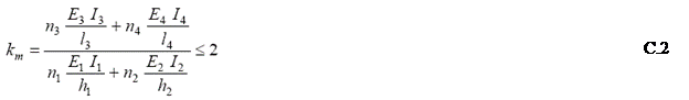 where
where
where the symbols have the meaning attributed to them in (2). above.
(4) If the eccentricity calculated in accordance with (2) above is greater than 0.45 times the thickness of the wall, the design may be based on (5) below.
(5) The eccentricity of loading to be used in design may be based on the load being resisted by the minimum required bearing depth, not taken to be more than 0, 1 times the wall thickness, at the face of the wall, stressed to the appropriate design strength of the material (see figure C.2).
 NOTE It should be borne in mind that basing the eccentricity on this Annex may lead to.sufficient rotation of the floor or beam to cause a crack on the opposite side of the wall to that of the load application.
Key
1) bearing depth ≤ 0, 1t
|
|